
By ‘mountaineergreen’
For some odd reason, Ford Motor Company failed to put cruise on my 1993 Ranger. I really missed cruise, so I looked into my options. I could add “factory” cruise from a donor vehicle, but removing the dash is necessary, not anything I want to do. Furthermore, the possibility of finding a suitable donor is slim to none given the high prices of scrap metal these days.
So, I got and Audiovox Cruise Control unit, CCS100. I looked into other brands, they were twice as high as this unit, $200 and above. I paid $84.99 for the CCS100 to my door from Amazon.
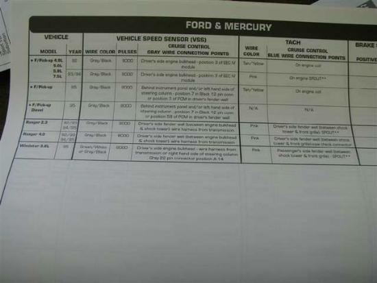
I got the installation manual ahead of time online, read through it a few times. It was helpful reading ahead and made the installation easier. I also went to the12volt.com and got the wiring colors for my truck. It tells the location and color of the wires pertinent to the installation of electrical components. It’s a great resource for all kinds of wiring projects.
This install is on my 1993 Ranger 3.0, but the process is similar for any vehicle.
I began by opening the box and looking at its contents:
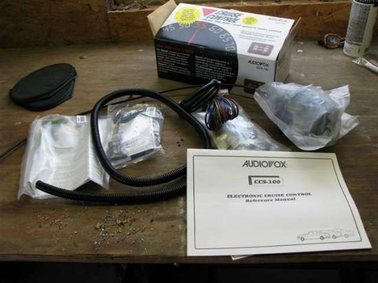
The kit came with every possible connector needed for installation in most every vehicle, plenty of wiring length, quality wire loom, instructions and a reference manual.
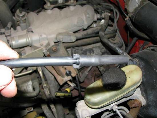
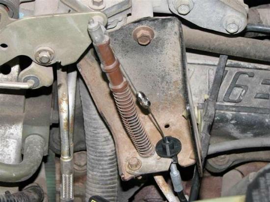
I removed the plastic throttle linkage cover from the truck-
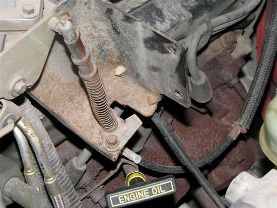
See the square hole in the bracket. That’s where the factory cruise connected.
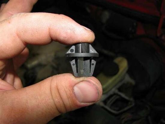
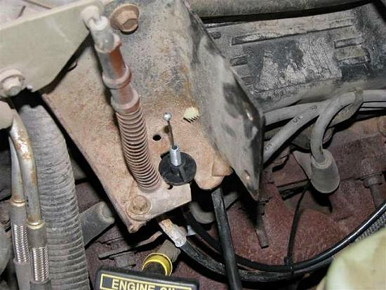
I found this adapter that fit the hole just right.
I put the adapter on the cable, sat the servo in the place where I wanted to mount it, routed the cable so that ended up running parallel with my throttle cable. Away from any heat or moving parts obviously. I took my time on this and made sure it was just right.
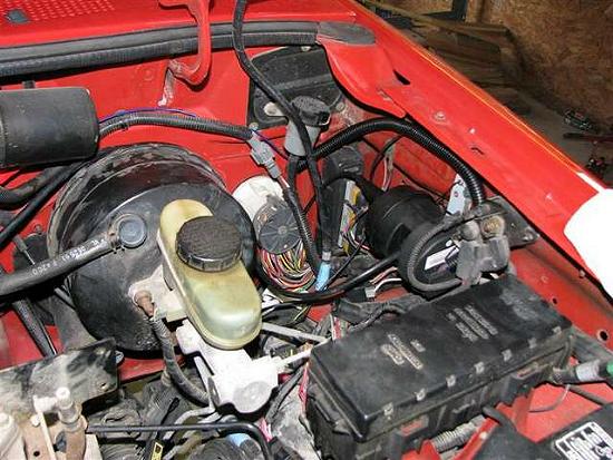
The servo was mounted on the driver’s side fender using the green ground screw just above the bracket. The servo grounds right there also. For now, I left it sitting loose until I made all the connections and set the DIP switches.
The servo requires a vacuum to run it. The best place is the tree on the back of the intake manifold.
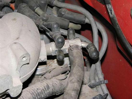
I found a suitable port, removed the cap.
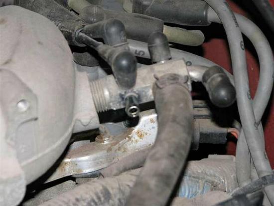
The port was larger than the line needed for the servo, so I used the included reducer and short piece of hose.
Then attached it to the tree, then the other end to the servo.
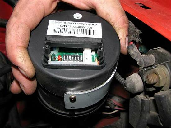
Set the DIP switches using the reference guide, all the information turned out to be spot on.
Now to run the wires through the firewall. All but two wires go through the firewall. The only two that stay are the VSS and Tach. I found a grommet in the perfect place, cut an X in it, slid it over the wires. Then I taped the wires to a dowel rod, pushed them through the hole.
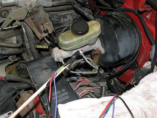
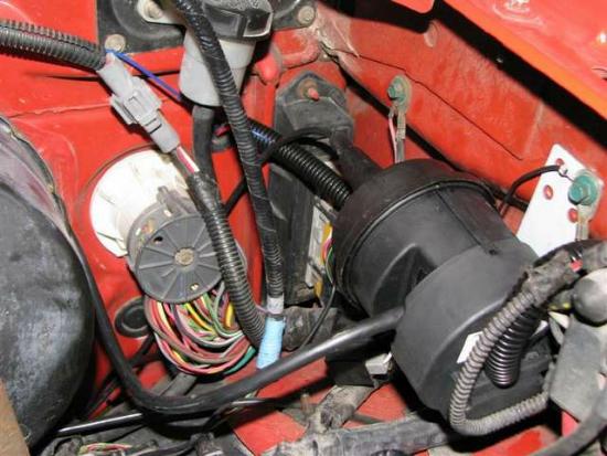
Servo mounted and grounded with the screw; wires loomed and ran through the firewall.
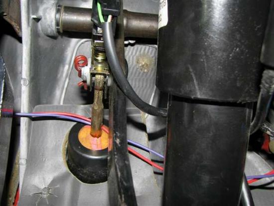
Wire loop ran over the stud, the connected to the servo cable. I had to adjust the adapter to leave just a little bit of slack in the cable.
The red and purple wires connect to the brake switch on the brake pedal. The red connects to the +12v constant, the purple connects to the other side, its +12v when the pedal is pressed.
The Brake Switch:
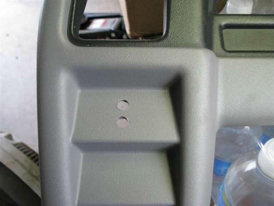
To Mount The Control Panel:
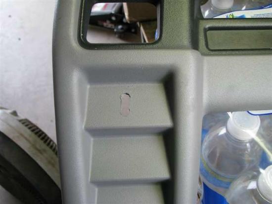
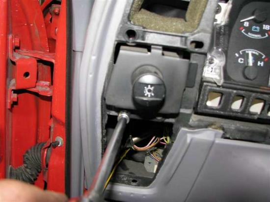
Drilled two holes, then cut the plastic between the holes. I removed the dash piece to do this.
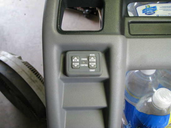
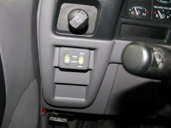
The control panel mounted with double sided tape, peel the backer and feed the wires through the hole, stick the panel on.
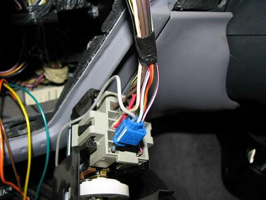
Put the colored wires in the connector per the instructions, there will be two wires left- one black, one grey. The black goes to a chassis ground; the grey goes to the instrument lamp lead for back lighting the switches. The headlight switch was right there, so I removed it to probe the wires and find the instrument lamp lead.
Use a scotch connector to connect the wires.
The Lighting:

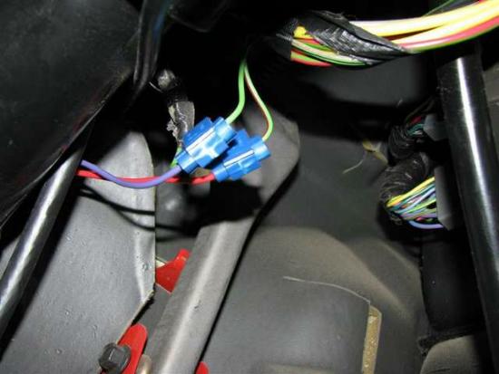
I found the VSS wire, right there near the bulkhead, grey with a black stripe just like the book said. I connected the wire from the servo to it.
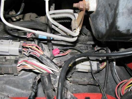
I don’t have a picture of it; the blue wire connects to the coil for a tach signal. The12volt.com said that the wire was on the coil, brown with a yellow stripe. I found that wire, but near the coil was not a suitable connection because the interference caused false deactivation of the cruise. I found what harness the wire ran in, followed it over to the bulkhead fitting that the wires passed through, then connected it there.
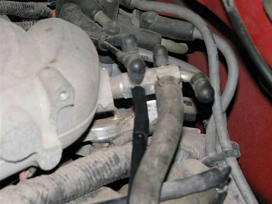
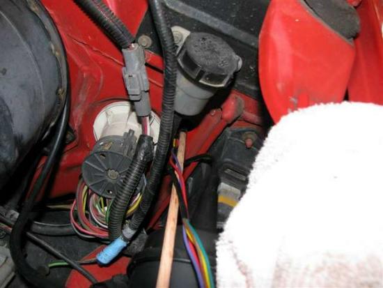
The nearly completed install (at this point the tach wire hadn’t been moved)
It works like any factory type cruise, nice smooth acceleration when resuming, hold the set speed well. This deactivates with brake signal, the off switch or a swift rev of the motor (like say I press in the clutch to shift).
Overall, I am very pleased with this, a nice product especially for its price. The instructions are not perfect, but pretty good, the reference manual is very complete though. The install took me about 4 hours and then a few minutes today to move the tach wire. Someone not so familiar with vehicles should expect a longer install time, but this is definitely doable by the do it yourselfer.
About The Author
Jim Oaks is the founder of TheRangerStation.com, the longest-running Ford Ranger resource online since 1999. With over 25 years of hands-on experience building and modifying Ford Rangers — including magazine-featured builds like Project Transformer — Jim has become one of the most trusted authorities in the Ford Ranger off-road and enthusiast space.
Since launching TheRangerStation.com, Jim has documented thousands of real-world Ranger builds, technical repairs, drivetrain swaps, suspension modifications, and off-road adventures contributed by owners worldwide. TheRangerStation.com has been referenced in print, video and online by enthusiasts, mechanics, and off-road builders looking for practical, and experience-based information.