Battling in the Ohio River Mud
Pictures Courtesy of Artic601 and Seneeb
During the American Civil War, the Union fought the Confederacy with its industry–the first “total war” in history. The foundation of what was to be the world’s mightiest industrial machine was laid along the banks of the Ohio River in Western Pennsylvania and Eastern Ohio. Coal, coke, iron, steel, lumber and textiles—all processed and shipped with the power of the river. This massive machine would build the track and machinery to connect the two oceans across our continent in the last half of the 19th century; build the skyscrapers during the industrial revolution at the turn of the century; supply Detroit with steel during the boom of the automobile; equip the United States and its allies through two World Wars; propel Western Europe through the aftermath and then, in the late 1960’s eventually falter as large, poorer nations took over the world’s heavy industry and the United States moved on toward high technology. As the foundries, factories and mills ground to a halt, the workers struggled briefly with the inevitable and then moved on in search of new lives. Behind them they left a landscape still bearing the scars of the many wars it fought. Large, open pit mines, hillsides opened up to remove their innards and large tracts of industrial land lying barren: the terrestrial casualty of a 100-year industrial war.
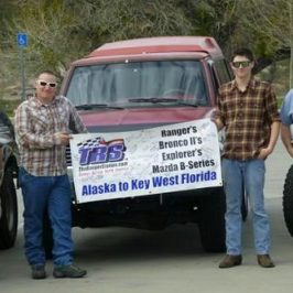
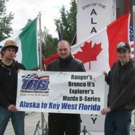
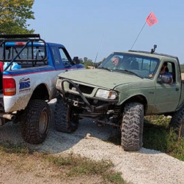
In a certain portion of this wasteland, a new battle has been taking place. Just kicking around in the dirt will yield evidence of the fight–small pieces of reflectors, torn tires, mauled fenders, shattered windshields hanging limply over rocks–even complete vehicles scatter the field. In April, two dozen TRS forum members converged on the field to take up arms against the terrain. Their weapons? Mud tires, transfer cases and fuel injection.
The first call-to-arms occurred during a cookout at TRS owner Jim Oaks’ headquarters. It seemed that an enemy regiment of nasty mud was getting out of hand and that a raid was in order to quell the disturbance. A platoon of twelve heavily armored Fords was hastily assembled and with the roar Super Swampers and glasspacks, the host road forth.
Though harassed by enemy saboteurs along the way (Jim Oaks’ fuel system was taken out by a satchel charge, for instance) the troop eventually reached the objective and immediately searched out and engaged the enemy. The fight was on.
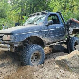
The Ranger’s attacked the mud in line-astern formation: each truck making a pass at the mud while the others circled protectively. The mud was eventually conquered but not before capturing several trucks (including my own), though they were soon liberated by TRS-1. In the end, the only casualty was GrayRanger98 whose front vacuum-hubs were apparently destroyed by a tidal wave of enemy yuck. The skirmish ended successfully, and everyone made it out, but the real battle was still to come. Orders were issued to rally the next morning and everyone departed for their bivouac. It was after 1AM.
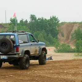
The next morning the host once again assembled. This time we had about two dozen trucks participating. Unfortunately, Jim had some pressing matters on the home front and left the platoon in the hands of his capable lieutenants: ErinBronco and JohnnyO. This time, TRS divided its forces in half and attacked in a classic two-pronged flanking maneuver with Erin Bronco’s “hard-core” group charging head on into the muck and Johnny O’s mostly stock group sweeping around and rolling up the flank.
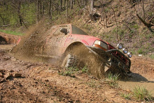
The hard-core group headed straight into the tank-traps and as the Rangers floundered through, war correspondent Jim Allen (on loan from 4Wheel Parts’ magazine Off-Road Adventures) was on hand to document the atrocities. Casualties at the pits were light with only PT Ranger’s full-size Bronco getting pinned down but subsequently rescued.
After the mud pits were routed the hard-core group played around on some small hills and ponds along the pipeline. Again, only one casualty was suffered as TRS member Brett_00’s brother’s Bronco II was captured by a pond. After his rescue Brett unleashed a punishing attack on the pond and then the hard-core formation moved on to storm a hill.
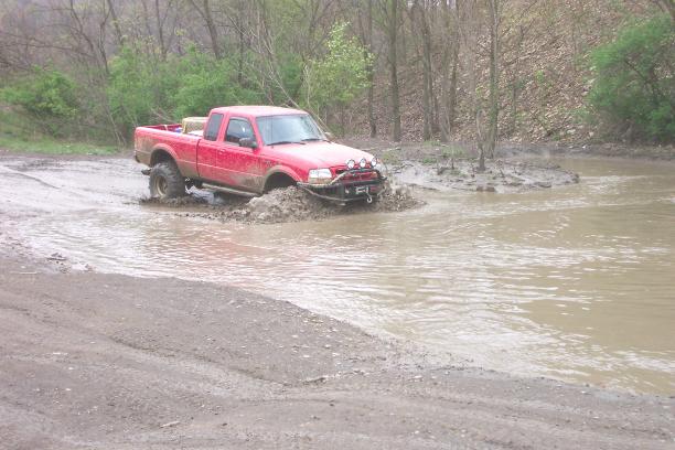
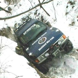
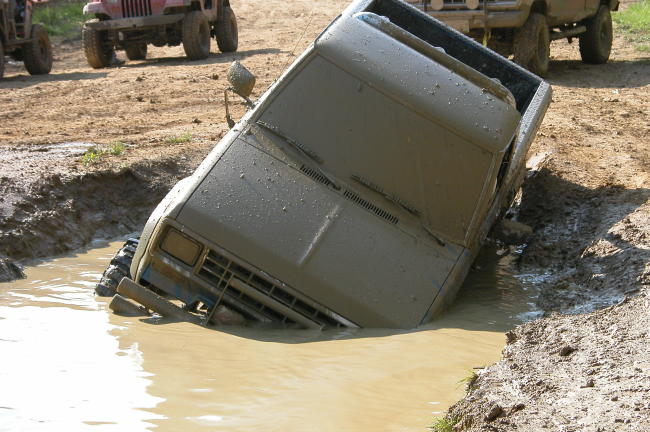
He did get stuck later in a mud hole. This photo became a locker advertisement for Randy’s Ring & Pinion

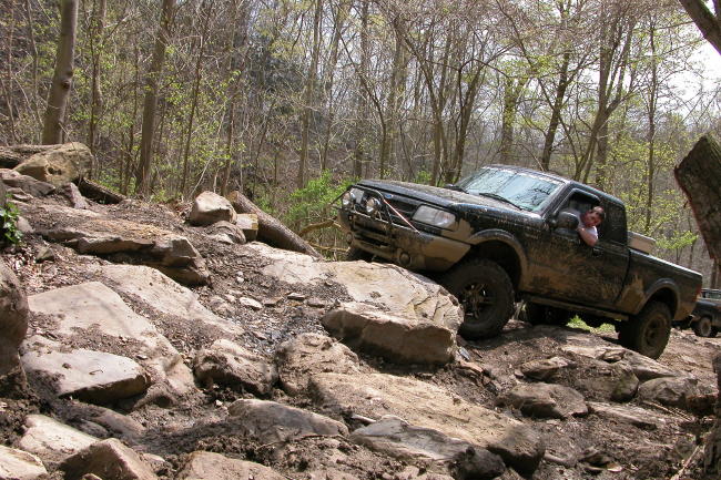
Meanwhile, the stockers under Johnny O circled around Wellsville and came in through a different entrance. Although I wasn’t cleared to attend the debriefing, I understand there was a nasty piece of work done on another portion of the power line hill in which TRS members Eric the Red and Wacky Woodchuck distinguished themselves by climbing the Powerline Hill.
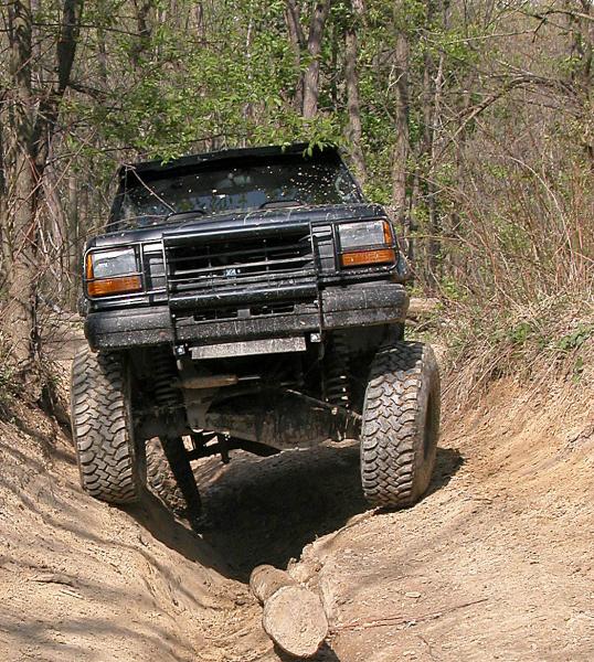
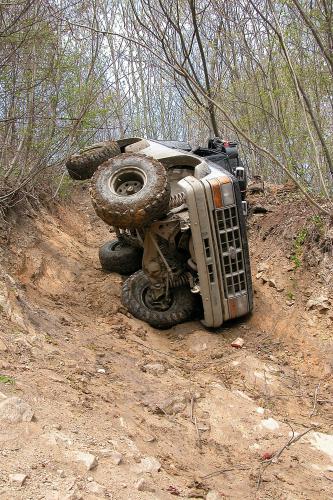
By this time the hard-core group had cleared their hill and was poised to creep down a steep trail full of switchbacks into the creek bed. One at a time with a safe interval between vehicles, the group crept down the hill. At several switchbacks the trucks were on three wheels trying to negotiate the steep turns. At least one forum member was able to save himself some hull damage by catching the truck from tipping with an arm out the window—not a recommended practice! But unfortunately, the hill claimed another casualty.
On one of the turns Ryan NWU peeled a tire off of the rim and his 6″ lifted Bronco II went over on its side. The campaign was delayed as the vehicle was being recovered. Damage was minimal and the group was soon on the move again.
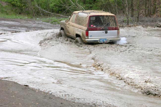
The stockers were apparently on the move themselves: moving through some mud. At least their trucks were pretty muddy when we met up with them at the rendezvous. Amazingly, the two-wheel-drive truck belonging to Seneeb managed not to get stuck. I guess there is something for everyone at Wellsville.
Meanwhile, the hard-core group made the tricky climb out of the creek bed and was soon back at the tank traps. At that point several of the members fanned out to engage in individual combat, and Jim Allen was on hand to get some pretty good shots of it. Notable among the show-offs was 351 Ranger in his awesome straight-axled V8 Ranger as he powered across a pond for the photographer. Later he would be sunk to the turret in a hole the size of a school bus.
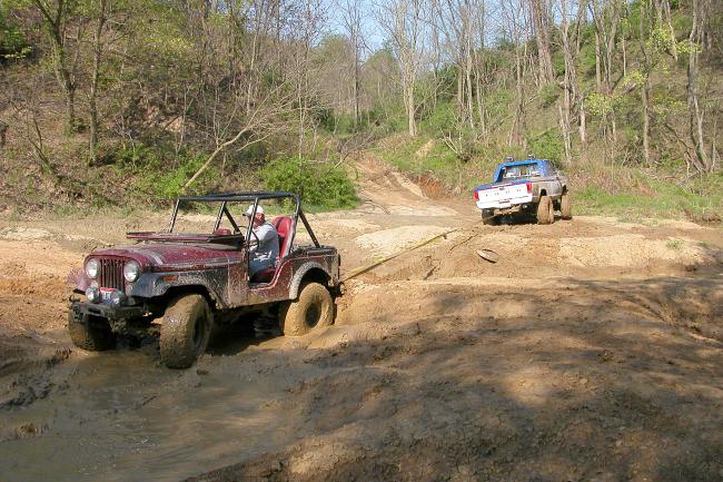
About this time the stocker group arrived on the scene followed closely by the appearance of Jim Oaks in his distinctive blue and white TRS 1. Although Jim had missed most of the day’s wheeling, he at least got to tow a bunch of Jeeps out of the mud holes. After the roges were all back from their individual adventures, Jim Oaks and Jim Allen held a drawing and passed out some cool prizes donated by TRS Round-Up sponsors 4Wheel Parts and Randy’s Ring & Pinion. Shortly afterwards, we parted ways and went back to our peaceful lives.

The Ohio River still pushes a trickle of barges down to the Mississippi and on to parts unknown. A scattered few mills still roll steel, and a few conveyors still run coal down the hillsides and into the barges. The former power of the valley faintly reverberates throughout the empty buildings and even emptier tracts of industrial land. But in at least one such tract it isn’t distant echoes that one hears. It is the sound of whining gears, howling Swampers and bellowing motors—signs that at least one type of steel still thrives in America.
About The Author
Will was a TRS Forum Moderator from 2001-2023 and has since retired from that role. He has been a very active contributor to The Ranger Station with experience modifying and off-roading Ford Ranger's and Bronco II's. Will's hobbies also include boat building, and he has built several boats. When not wrenching on trucks or building boats, Will likes to write and has written two books. Will has the ability to take the simplest adventures and make them fascinating to read about. We have always enjoyed his storis and contributions.