I have not. What would be the best way to do this and what am I testing for? I've got a meter and all those other goodies, so now all I need is the knowledge.
A quick search shows there are some after market units- is there any performance gain with them? Has anyone used the flame thrower or accel?
I just went and copied this from another site
Ford EEC-IV, and TFI Diagnostics Manual
Table of Contents:
Self-Diagnostics Terminal Setup…………………………………………………...1
Code erasing…………………………………………………………………………2
Two Digit Test Codes……………………………………………………………….3
Three Digit Test Codes……………………………………………………………..4
Abbreviations and Definitions……………………………………………………….5
TPS Calibration………………………………………………………………………6
Base Idle Adjustment………………………………………………………………..7
Oxygen Sensor Testing……………………………………………………………..8
TFI Module Testing………………………………………………………………….9
ACT/ECT Test………………………………………………………………………10
TFI Timing Procedure………………………………………………………………11
IAC Cleaning and Testing………………………………………………………….12
FPR Testing…………………………………………………………………………13
Knock Sensor……………………………………………………………………….14
MAP Test……………………………………………………………………………15
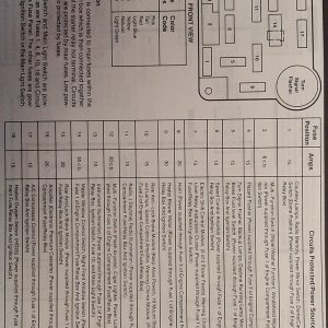
Self-Diagnostics Terminal Setup (1)
On the passenger’s side, under the hood, there is the computer’s self-diagnostics output terminal. It is usually red or gray in color, and has a distinctive shape as shown below. An easy way to utilize this terminal without an expensive scan tool is with an analog multi-meter, set on DC Voltage (20V setting, or nearest equivalent). The Positive lead of the multi-meter can be attached to the battery’s (+) terminal, and the negative lead of the multi-meter can be attached to the connection as below. A jumper wire is also necessary (as below).
Scanning the codes. You want to make sure the engine is fully warmed up, automatic transmission in park, or manual transmission in neutral, with the parking brake on, or the wheels blocked. Once the multi-meter is attached, turn the ignition on, and watch the needle. Codes will be displayed as needle sweeps in groups of 2 or 3, followed by a 6 second delay. A 2 or three digit code will be several quick sweeps (1-9) followed by a 1 second pause, than the next number. These are referred to as memory codes. This test is complete when code 11 (system pass) has been displayed.
Running codes are done after this. The engine is started and left running. The code reader will flash twice (for a four cylinder) three times (for a 6 cylinder), four times (for and 8 cylinder), and five times (for a diesel). The computer will test items, including the timing. A timing light may also bee hooked up, and the timing should advance by 20 degrees during this test. Eventually there will be a single quick sweep of the needle; this is the throttle goose test. When this happens, the throttle must be depressed (a minimum) of 25%. The codes will be soon to follow, as per the previous test.
Erasing Codes (2)
Codes automatically erase after 60-100 starts. Starting the memory test procedure, and unplugging the connections erases memory codes. Disconnecting the battery will also erase all the codes; however, this may trigger a code 19 (loss of PCM power).
Two Digit Codes: (3)
11 System checks OK -
12 Idle Speed Control motor or Air Bypass not controlling idle properly (generally idle too low) - ISC
13 (O) ISC did not respond properly (extends to touch throttle then retracts for KOEO) - ISC
(R) Idle Speed Control motor or Air Bypass not controlling idle properly (generally idle too high)
(M) ISC sticking, open ITS circuit or TP sticking
14 Ignition pickup was erratic - Ignition Systems
E4OD Transmission diesel RPM sensor - Diesel RPM sensor
15 (O) No Keep Alive Memory power to PCM pin 1 or bad PCM (Memory Test Failure)
(M) KAM (pin 1) was interrupted (was battery disconnected ?)
16 1.9L & 2.5L - Throttle stop set too high - IDLE or Idle Set Procedures
2.3L - RPM's too low - IDLE
(O) Electronic ignition - IDM circuit fault - Ignition Systems
17 1.9L & 2.5L - Throttle stop set too low - IDLE
18 (R) Check base timing & advance function - Timing Tests
(M) Ignition TACH signal erratic - Ignition Systems
19 (O) No Vehicle Power (pins 37 + 57) or bad PCM VPWR Diagnosis
(R) Erratic idle during test (reset throttle & retest) - Idle Set Procedures
Electronic ignition Cylinder ID sensor/circuit problem - Ignition Systems
21 Engine Coolant Temperature (ECT) sensor out of range - ECT
22 MAP (vacuum) or BARO signal out of range - MAP
23 Throttle sensor out of range or throttle set too high - TPS
24 Intake Air Temperature (IAT) or Vane Air Temperature (VAT) sensor out of range - IAT VAT
25 Knock sensor not tested (ignore if not pinging) - KS
26 Mass Air Flow (MAF) or Vane Air Flow (VAF) out of range - MAF VAF
Transmission Oil Temperature (TOT) sensor out of range - Transmissions
27 Vehicle Speed Sensor problem - VSS
28 Vane Air Temperature (VAT) sensor out of range - VAT
2.3L w/Electronic Ignition - Cyl ID, IDM low or right coil pack failure - Ignition Systems
29 Vehicle Speed Sensor problem - VSS
EGR CODES DEPEND ON WHAT SYSTEM TYPE THE VEHICLE IS EQUIPPED WITH:
EVP is for vehicles equipped with EGR solenoid(s), with or without an EVP sensor
EVR is for vehicles equipped with an EGR Vacuum Regulator (EVR) and an EGR Valve Position (EVP) sensor
PFE is for vehicles with Pressure Feedback EGR (PFE) sensor and and an EGR Vacuum Regulator (EVR)
If you don't know what type of system you have, go to the EVP heading, which is the first one.
There are pictures under the different headings to help you identify the system.
31 EVP - (O, R, M) EVP signal is/was out of range - EVP
EVR - (O, R, M) EVP signal is/was low - EVR
PFE - (O, R, M) PFE signal is/was low - PFE
32 EVP - (R) EGR not responding properly during test - EVP
EVR - (O, R, M) EVP signal is/was low - EVR
PFE - (R, M) PFE shows low pressure, EGR not seating or memory, not seating intermittently - PFE
33 ALL - (O, M) EGR did not open/ respond during test or if memory code, did not open intermittently - EVP EVR PFE
34 EVP - (R) EGR did not respond properly during test - EVP
EVR - (O, R, M) EVP sensor is/was high - EVR
PFE - (O, R, M) PFE sensor is/was out of range - PFE
35 EVP - (R) Engine RPM's too low to test EGR system - EVP
EVR - (O, R, M) EVP sensor signal is/was high - EVR
PFE - (O, R, M) PFE sensor signal is/was high - PFE
38 Idle Tracking Switch signal was intermittent - ISC
39 Transmission Torque Converter clutch not engaging - Transmissions
40 SERIES FUEL/AIR INJECTION CODES ON VEHICLES WITH DUAL OXYGEN SENSORS REFER TO THE RIGHT OR REAR SENSOR. EXCEPT: 1984-1988 3.8L ENGINES: LEFT SENSOR
41 (R) System lean - Fuel control
(M) System was lean for 15 seconds or more (no HO2S switching) - Fuel control
42 (R) System rich - Fuel control
(M) System was rich for 15 seconds or more (no HO2S switching) - Fuel control
43 (R) HO2S sensor not reading (run at 2000 rpm's for 2 minutes and retest - check for HO2S switching)
(M) Was lean at WOT for 3 seconds or more - Fuel control
44 AIR system inoperative - Air Injection
45 AIR not Diverting (AIRD) - Air Injection
Electronic Ignition - coil primary circuit failure - Ignition Systems
46 AIR Bypass (AIRB) not working - Air Injection
Electronic Ignition - primary circuit failure coil 2 - Ignition Systems
47 Low flow un-metered air (check for small vacuum leaks, injector o-rings, gaskets etc.)
E4OD transmission 4x4 switch/circuit problem - Transmissions
48 High flow un-metered air (check for large vacuum leak, inlet hoses etc.)
Electronic Ignition - coil primary circuit failure - Ignition Systems
49 Electronic Ignition - spout signal circuit problem - Ignition Systems
Transmission 1/2 shift problem - Transmissions
51 Engine Coolant Temperature (ECT) sensor signal is/was too high - ECT
52 Power Steering Pressure Switch/circuit open - PSP
(R) Did you turn wheel during test ?
53 Throttle Position sensor too high - TPS
54 Intake Air Temperature (IAT) or Vane Air Temperature (VAT) signal high - IAT VAT
55 No or low (under 7.5 V) Key Power to PCM pin 5
56 Vane Air Flow (VAF) or Mass Air Flow (MAF) sensor high - VAF MAF
Transmission Oil Temperature sensor too high - Transmissions
57 Intermittent in Park/Neutral/ Switch or Neutral Pressure switch circuit - PNP or Transmissions
1990 Scorpio - Octane jumper installed (information only code - to inform you if it is installed or not)
58 Idle Tracking Switch (ITS) signal problem ISC
Vane Air Temperature (VAT) sensor out of range or open - VAT
59 AXOD 4/3 circuit fault - Transmissions
3.0L SHO - Low speed fuel pump circuit problem - Power / Fuel Pump Circuits
Transmission 2/3 shift problem - Transmissions
1990 Scorpio - Idle jumper installed (information only code - to inform you if it is installed or not)
61 Engine Coolant Temperature (ECT) sensor is or was too low - ECT
62 AXOD (KOEO only) 3/2 circuit short to ground - Transmissions
AXOD (KOEO AND KOER) 4/3 circuit failure - Transmissions
E4OD excessive converter clutch slippage - Transmissions
63 Throttle Position Sensor (TPS) signal too low TPS
64 Intake Air Temperature (IAT) or Vane Air Temperature (VAT) signal low or grounded - IAT VAT
65 Check intermittent HO2S (signal or ground) - Fuel Control
(R) E4OD truck - cycle OD cancel switch after engine ID is received - Transmissions
1984 3.8L ONLY - O, M Battery voltage high (check for electrical system overcharging)
66 Vane Air Flow (VAF) or Mass Air Flow (MAF) signal low - VAF MAF
Transmission Oil Temperature (TOT) signal low (possibly grounded) - Transmissions
67 Park/Neutral circuit fault - PNP
Transmission Manual Lever Position (MLP) sensor circuit - Transmissions
(M) Intermittent Park Neutral Position (PNP) sensor fault - PNP
68 Idle Tracking Switch (ITS) circuit (possibly grounded) - ISC
Vane Air Temperature (VAT) sensor out of range or grounded - VAT
3.8L AXOD -Transmission Temperature Switch (TTS) open - Transmissions
Electronic Transmission - Transmission Oil Temperature (TOT) sensor was overheated - Transmissions
69 AXOD transmission (O) 3/2 switch closed (possible short circuit) - Transmissions
AXOD (M) 3/2 switch open (possible short to power) - Transmissions
E4OD 3/4 shift problem - Transmissions
70 (M) 3.8L AXOD - Data link to instrument cluster fault. Service any other EEC codes, erase memory and retest.
If code is still present refer to instrument cluster diagnosis manual.
71 (M) 1.9L TBI, 2.3L TBI, 2.5L TBI - ITS signal was grounded when throttle should have been opening ITS - ISC
ISC motor problem or Idle Tracking Switch (ITS) signal wire shorted to ground - ISC
(M) 1.9L MFI - PCM re-initialized. Possible electrical noise, case ground or intermittent VPWR problem - VPWR Diagnosis
(M) 3.8L AXOD - Data link to instrument cluster fault - See code 70
72 (R) No MAP or MAF change in "goose" test - retest, check for frequency or voltage change - MAP MAF
(M) 1.9L MFI - VPWR circuit to PCM was intermittent - VPWR Diagnosis
(M) 2.3L T/C - PCM re-initialized. Possible electrical noise, case ground or intermittent VPWR problem - VPWR Diagnosis
(M) 3.8L AXOD - Message center data link circuit fault - See code 70
73 (O) Rerun test, if 73 is still output replace TPS
(R) No Throttle Position Sensor (TPS) change in "goose" test. Must get at least 25% throttle rotation - TPS
74 Was brake depressed after engine ID was received ?
Brake On Off (BOO) signal open or short to ground - BOO
75 Brake On Off (BOO) signal shorted to power - BOO
76 Vane Air Flow (VAF) did not respond to "goose" test - VAF
77 System did not receive "goose" test - see TESTS
78 (M) VPWR circuit to PCM was intermittent or the PCM is bad VPWR Diagnosis
79 A/C is on or pin 10 is shorted to power
80 SERIES CODES GENERALLY ARE CIRCUIT PROBLEMS THAT COULD BE WIRING, RELAY OR SOLENOID RELATED.
ONLY ONE OF THE CIRCUITS LISTED UNDER THE CODE IS USED ON EACH VEHICLE. THE FAULT IS IN WHICHEVER SOLENOID OR CIRCUIT IS PRESENT ON THE VEHICLE
81 Boost control solenoid - Solenoids
AIRD solenoid - Solenoids and Air Injection
3.0L SHO - Inlet Air Solenoid - Solenoids
82 2.3L TC - Fan Control wire shorted to ground - A/C and Fan Circuits
AIRB solenoid - Solenoids and Air Injection
3.8L SC - Super Charger Bypass Solenoid - Solenoids
83 High Electro Drive Fan circuit fault - A/C and Fan Circuits
EGR Control solenoid - Solenoids
3.0L SHO - Low Speed Fuel Pump Relay circuit - Power / Fuel Pump Circuits
84 EGR Vacuum Regulator - Solenoids
EGR cutoff solenoid - Solenoids
EGR Vent solenoid - Solenoids
85 2.3L T/C Automatic - 3/4-4/3 Shift solenoid - Transmissions
CANP solenoid (ALL 1989) - Solenoids
(M) 1.9L MFI - System has corrected rich condition - Fuel control
86 2.3L or 2.9L Truck - A4LD 3/4 shift solenoid - Transmissions
(M) 1.9L MFI - System has corrected lean condition - Fuel control
87 (O) Fuel pump circuit fault (check inertia switch) - Power / Fuel Pump Circuits
Vehicles with 2BBL carb - Temperature Compensated Accelerator Pump Solenoid - Solenoids
(M) intermittent in fuel pump primary circuit - Power / Fuel Pump Circuits
NOTE: On some Escorts with automatic seat belts this code is normal IN MEMORY due to the wiring
88 Throttle Kicker Solenoid - Solenoids
Variable Voltage Choke relay circuit fault - VVC
Fan Control circuit fault - A/C and Fan Circuits
A4LD - Converter Clutch Override solenoid - Transmissions
Electronic Ignition - IDM, DPI or spout circuit fault - Ignition Systems
89 A4LD - Converter Clutch Override solenoid - Transmissions
AXOD Torque Converter Control solenoid circuit - Transmissions
Exhaust Heat Control (heat riser) solenoid circuit - Solenoids
90 SERIES FUEL/AIR INJECTION CODES ON VEHICLES WITH DUAL OXYGEN SENSORS REFER TO THE LEFT OR FRONT SENSOR. EXCEPT: 1984-1988 3.8L ENGINES: RIGHT SENSOR
91 (R, M) System running lean - Fuel control
Transmission SS 1 circuit/solenoid problem - Transmissions
92 (R) System running rich - Fuel control
Transmission SS 2 circuit/solenoid problem - Transmissions
93 (O) Throttle linkage binding or bad ISC motor ISC (R) HO2S not reading - Fuel control
Transmission TCC circuit/solenoid problem - Transmissions
94 AIR system inoperative - Air Injection
Transmission TCC circuit/solenoid problem - Transmissions
95 (O) Fuel pump: open, bad ground or always on - Power / Fuel Pump Circuits
(R) AIR not Diverting (AIRD) - Air Injection
(M) Possible bad fuel pump ground or open between fuel pump and pin 8 at PCM (Fuel Pump Monitor signal) - Power / Fuel Pump Circuits
96 (O) Fuel pump monitor circuit shows no power - Power / Fuel Pump Circuits
(R) AIR Bypass (AIRB) not working - Air Injection
(M) (Service 87 code first if present) Fuel pump relay or battery power feed was open - Power / Fuel Pump Circuits
97 E4OD OD cancel light circuit failure - Transmissions
98 (R) Did not pass KOEO yet (Get 11 in KOEO first)
Transmission EPC circuit/solenoid failure - Transmissions
99 (R) ISC needs to learn (Let idle for 2 minutes; Erase memory and retest)
Transmission EPC circuit/solenoid failure - Transmissions
Three Digit Codes: (4)
111 System checks OK
112 (O,M) Intake Air Temperature (IAT) sensor is/was low or grounded - IAT
113 (O,M) IAT sensor is/was high or open - IAT
114 (O,R) IAT sensor out of range - IAT
116 (O,R) Engine Coolant (ECT) sensor out of range - ECT
117 (O,M) ECT sensor is/was low or grounded - ECT
118 (O,M) ECT sensor is/was high or open - ECT
121 (O,R,M) Throttle Position (TP) sensor out of range - TPS
122 (O,M) TP low (possibly grounded or open circuit) - TPS
123 (O,M) TP is/was high or short to power - TPS
124 (M) TP voltage was higher than expected - Fuel control
125 (M) TP voltage was lower than expected - Fuel control
126 (O,R,M) MAP or BARO sensor out of range - ">MAP
128 (M) MAP vacuum has not been changing - check vacuum lines - ">MAP
129 (R) No MAP or Mass Air Flow sensor change during "goose" test - MAP MAF
136 (R) Oxygen sensor not switching/system lean Left or Front HO2S - Fuel control
137 (R) Oxygen sensor not switching/system rich Left or Front HO2S - Fuel control
138 (R) Fault in Cold Start Injector circuit - Fuel control
139 (M) Oxygen sensor not switching Left or Front HO2S - Fuel control
144 (M) Oxygen sensor not switching Single, Right or Rear HO2S - Fuel control
157 (R,M) Mass Air Flow signal is/was low or grounded - MAF
158 (O,R,M) MAF sensor is/was high or short to power - MAF
159 (O,R) MAF sensor is/was out of range - MAF
167 (R) No Throttle Position sensor change in "goose" test (must get at least 25% rotation) - TPS
171 (M) Oxygen sensor not switching - system was at adaptive limits - Single, Right or Rear HO2S - Fuel control
172 (R,M) Oxygen sensor not switching - system is or was lean - Single, Right or Rear HO2S - Fuel control
173 (R,M) Oxygen sensor not switching - system is or was rich - Single, Right or Rear HO2S - Fuel control
174 (M) Oxygen sensor was slow in switching Single, Right or Rear HO2S - Fuel control
175 (M) Oxygen sensor not switching - system was at adaptive limits - Left or Front HO2S - Fuel control
176 (M) Oxygen sensor not switching - system is or was lean Left or Front HO2S - Fuel control
177 (M) Oxygen sensor not switching - system was rich Left or Front HO2S - Fuel control
178 (M) Oxygen sensor was slow in switching Left or Front HO2S - Fuel control
179 (M) Fuel system was rich at part throttle Single, Right or Rear HO2S - Fuel control
181 (M) Fuel system was lean at part throttle Single, Right or Rear HO2S - Fuel control
182 (M) Fuel system was rich at idle Single, Right or Rear HO2S - Fuel control
183 (M) Fuel system was lean at idle Single, Right or Rear HO2S - Fuel control
184 (M) Mass Air (MAF) output higher than expected - Fuel control
185 (M) Mass Air (MAF) output lower than expected - Fuel control
186 (M) Injector pulse width longer than expected or Mass Air Flow (MAF) lower than expected - Fuel control
187 Injector pulse width shorter than expected or Mass Air Flow (MAF) higher than expected - Fuel control
188 (M) Fuel system was rich at part throttle - Left or Front HO2S - Fuel control
189 (M) Fuel system was lean at part throttle - Left or Front HO2S - Fuel control
191 (M) Fuel system was rich at idle - Left or Front HO2S - Fuel control
192 (M) Fuel system was lean at idle - Left or Front HO2S - Fuel control
193 Failure in Flexible Fuel (FF) sensor circuit - Fuel control
194 (M) Perform cylinder balance test to check for inoperative injectors
195 (M) Perform cylinder balance test to check for inoperative injectors
211 (M) Ignition PIP signal was erratic or missing - Ignition Systems
212 (M) Ignition TACH signal was erratic (module/wiring) or SPOUT circuit fault - Ignition Systems
213 (R) Ignition SPOUT or SAW circuit open or shorted - Ignition Systems
214 (M) Error in Cylinder ID (CID) circuit or signal - Ignition Systems
215 (M) Primary circuit failure - ignition coil 1 - Ignition Systems
216 (M) Primary circuit failure - ignition coil 2 - Ignition Systems
217 (M) Primary circuit failure - ignition coil 3 - Ignition Systems
218 (M) IDM signal open or high or left coil pack failure - Ignition Systems
219 (M) SPOUT circuit failure, timing defaulted to 10 degrees - follow code 213 diagnosis
222 (M) IDM open or high or right coil pack failure - Ignition Systems
223 (M) Dual Plug (DPI), SPOUT or IDM circuit fault - Ignition Systems
224 (M) Failure in ignition coil primary circuit - Ignition Systems
225 (R) Knock sensor not tested (ignore if not pinging) - KS
226 (O) Ignition Diagnostic Monitor (IDM) signal fault - Ignition Systems
232 (M) EI primary coil circuit failure - Ignition Systems
238 (M) EI primary circuit failure - ignition coil 4 - Ignition Systems
311 (R) AIR system not working - Single, Right or Rear HO2S - Air Injection
312 (R) AIR not diverting - Air Injection
313 (R) AIR not bypassing - Air Injection
314 (R) AIR inoperative, Left or Front HO2S - Air Injection
326 (R,M) Pressure Feedback EGR shows low pressure EGR not seating or not seating intermittently - PFE
327 (O,R,M) EGR feedback signal is/was low - EVR or PFE
328 (O,R,M) EGR Valve Position (EVP) is/was low - EVR
332 (R,M) EGR did not open/respond during test or if memory code, did not open intermittently - EVR or PFE
334 (O,R,M) EVP sensor is/was high - EVR
335 (O) EGR feedback signal is/was out of range - EVR or PFE
336 (O,R,M) PFE sensor signal is/was was high - ">PFE
337 (O,R,M) EGR feedback signal is/was was high - EVR
338 (M) Cooling system did not heat up (check cooling system / thermostat operation)
339 (M) Cooling system overheated (check cooling system / thermostat operation)
341 (O) Octane jumper installed (information only code to notify you if it is installed)
411 (R) Idle speed system not controlling idle properly (generally idle too high) - ISC
412 (R) Idle speed system not controlling idle properly (generally idle too low) - ISC
452 (M) Vehicle Speed Sensor (VSS) problem
511 (O) No power to PCM pin 1 or bad PCM (processor)
512 (M) Memory power (PCM pin 1) was interrupted - Was battery disconnected ?
513 (O) Replace processor (PCM) (internal failure)
519 (O) PSP switch/circuit open - PSP
521 (R) Wheel not turned during test or PSP problem - PSP
522 (O) Park/Neutral Position (PNP) or Clutch Pedal Position (CPP) circuit fault - PNP
transmission MLP sensor out of range in park - Transmissions
524 Problem in low speed fuel pump circuit - Power / Fuel Pump Circuits
525 (O,M) Park/Neutral Position (PNP) or Clutch Pedal Position (CPP) circuit fault - PNP
528 (M) System shows voltage at pin 10 (is A/C on ?) or pin 30 (PNP, CPP switch) - PNP
529 (M) Data Communications Link to processor failure
Service any EEC codes, erase memory and retest. If code is still present refer to instrument cluster diagnosis manual.
533 (M) Data Communications Link to instrument cluster failure - see 529
536 (O,R,M) Brake On Off open or shorted to ground - BOO
538 (R) System did not receive "goose" test - TESTS
539 (O) System shows voltage at PCM pin 10. Is A/C on ?
542 (O,M) Fuel pump open, bad ground or always on - - Power / Fuel Pump Circuits
543 (O) Fuel pump monitor circuit shows no power - Power / Fuel Pump Circuits
(M) (Service 556 code first if present) Fuel pump relay or battery power feed was open - Power / Fuel Pump Circuits
551 Problem in Intake Manifold Runner Control (IMRC) solenoid/circuit - Solenoids
552 (O) AIRB solenoid/circuit failure - Solenoids
553 (O) AIRD solenoid/circuit failure - Solenoids
554 (O) Fuel Press Regulator Control solenoid/circuit fault - Power / Fuel Pump Circuits
556 (O,M) Fuel pump relay primary circuit fault - Power / Fuel Pump Circuits
557 (O,M) Low speed pump relay primary circuit fault - Power / Fuel Pump Circuits
558 (O) EGR vacuum regulator solenoid/circuit failure - EVR or PFE or Solenoids
559 (O) A/C relay primary circuit fault - A/C and Fan Circuits
563 (O) High Fan Control (HFC) circuit failure - A/C and Fan Circuits
564 (O) Fan Control (FC) circuit failure - A/C and Fan Circuits
565 (O) Canister Purge 1 solenoid/circuit failure - Solenoids
566 (O) transmission 3/4 shift solenoid/circuit - Transmissions
569 (O) Canister Purge 2 solenoid/circuit failure - Solenoids
578 (M) A/C pressure sensor VREF short to ground - A/C and Fan Circuits
579 (M) ACP sensor did not change with A/C on - A/C and Fan Circuits
581 (M) Cooling fan current was excessive - A/C and Fan Circuits
582 (O) Open cooling fan circuit - A/C and Fan Circuits
583 (M) Fuel pump current was excessive - Power / Fuel Pump Circuits
584 (M) Open power ground circuit - Power / Fuel Pump Circuits
585 (M) A/C clutch current was excessive - A/C and Fan Circuits
586 (M) Open circuit in A/C clutch - A/C and Fan Circuits
587 (O, M) Communication problem between PCM and Variable Control Relay Module (VCRM) - Power / Fuel Pump Circuits
617 (M) Transmission shift failure (1/2 shift) - Transmissions
618 (M) Transmission shift failure (2/3 shift) - Transmissions
619 (M) Transmission shift failure (3/4 shift) - Transmissions
621 (O) Solenoid/circuit failure - shift solenoid 1 - Transmissions
622 (O) Solenoid/circuit failure - shift solenoid 2 - Transmissions
624 (O,M) Solenoid/circuit failure -Electronic Pressure Control (EPC) current is high - Transmissions
625 (O,M) Solenoid/circuit failure - Electronic Pressure Control (EPC) current is low - Transmissions
626 (O) Transmission Coast Clutch (CCS) Solenoid/circuit fault - Transmissions
627 (O) Torque Converter Clutch circuit fault - Transmissions
628 (M) Excessive converter clutch slippage - Transmissions
629 (O,M) Torque Converter Clutch circuit fault - Transmissions
631 (O) Overdrive Cancel Light circuit problem - Transmissions
632 (R) E4OD - Transmission Control Switch (TCS) should be cycled once between engine ID and Goose test
633 (O) 4x4L switch should be in 4x2 or 4x4 high for the test
634 (O,M) Park/Neutral Position (PNP) or Clutch Pedal Position (CPP) circuit fault
Electronic shift transmission - Manual Lever Position (MLP) sensor out of range in PARK - Transmissions
636 (O,R) Transmission Oil Temperature (TOT) sensor out of range - Transmissions
637 (O,M) TOT sensor is/was high or open - Transmissions
638 (O,M) TOT sensor is/was low or grounded - Transmissions
639 (R,M) Transmission Speed sensor (TSS) circuit fault - Transmissions
641 (O) Transmission solenoid/circuit failure Shift Solenoid 3 - Transmissions
643 (O)(M) Torque Converter Clutch (TCC) circuit - Transmissions
645 (M) Transmission 1st gear failure - Transmissions
646 (M) Transmission 2nd gear failure - Transmissions
647 (M) Transmission 3rd gear failure - Transmissions
648 (M) Transmission 4th gear failure - Transmissions
649 (M) Transmission EPC system failure - Transmissions
651 (M) Transmission EPC solenoid/circuit fault - Transmissions
652 (O) Torque Converter Clutch (TCC) circuit fault - Transmissions
654 (O) Transmission selector not in PARK - Transmissions
656 (M) Torque Converter Clutch (TCC) slip - Transmissions
657 (M) Transmission temperature was excessive - Transmissions
998 (R) Did not pass Key On Engine Off test yet (Get 111 in KOEO first)
Abbreviations & Definitions: (5)
ACT: Air Charge temperature sensor. Senses the temperature of air entering the engine.
BP: Barometric Pressure (see MAP)
EEC: Electronic Engine Control Ford’s Engine management systems.
ECT: Engine Coolant Temperature Sensor. Senses the coolant temperature.
EGR: Exhaust Gas Re-circulation Valve. Allows some harmful exhaust gasses to be re-burned through the engine for emissions purposes.
EVP: EGR Valve Position sensor.
FPR: Fuel Pressure Regulator. A vacuum actuated device to keep constant fuel pressure.
HEGO: Heated Exhaust Gas Oxygen sensor (O2 sensor, EGO, oxygen sensor). Detects how much oxygen is in the exhaust to determine rich or lean running conditions.
IAC/ISC: Idle Air Control (Idle Speed Control) motor. An electric valve which allows air to enter the intake at idle, changing the idle speed.
IAT: Intake Air Temperature (see ACT)
KS: Knock Sensor. Detects Engine Knock (vibration) to allow computer to adjust timing accordingly
KOEO (O): Key On, Engine Off. Type of diagnostics test.
KOER (R): Key On, Engine Running. Type of diagnostics test.
MAF: Mass Air Flow Sensor
MAP: Manifold Absolute Pressure sensor.
MIL: Malfunction Indication Lamp (Check Engine Light on Dash)
MLP: Manual Lever Position.
OBD: On Board Diagnostics (the computer’s diagnostics system)
PCM: Power train Control Module (the computer)
PIP: Computer Input for Timing Indication.
PNP: Park/Neutral Position Sensor. Senses if an automatic is in park, or a standard is in neutral. Also referred to as a Neutral Safety Switch.
SPOUT: Spark Output. It is a distributor to allow manual control for ignition timing. It is also the output signal of the distributor to the PCM.
TFI: Thick Film Ignition. A Ford Ignition module, which is found at the base of the distributor.
TP (TPS): Throttle Position Sensor. Tells the PCM how much gas should be entering the Engine.
VSS: Vehicle Speed Sensor.
TPS Calibration: (6)
Warm the engine up. Shut engine off, and turn ignition on. With a voltmeter on the appropriate setting, probe the TPS center wire with the (+) probe, and ground the (-) probe. Adjust the throttle plate adjustment screw so the voltmeter’s reading is 0.9 to 1.0V DC.
Base Idle Adjustment: (7)
This essentially is an alternate test for the TPS Calibration. The base idle is computer controlled via the Idle Air Control (IAC) motor. To do this crude base adjustment, warm the engine up. Unplug the IAC electrical connector. Restart the engine (if it doesn’t start, screw the throttle plate adjustment screw in, until it starts). Once the vehicle is running, adjust the throttle plate adjustment screw until the idle reaches 650RPM. Plug the IAC electrical connector, and restart the engine. The idle should settle to 850-950RPM. Note that it is best to use an accurate tune up tachometer, not the stock gauge.
Oxygen Sensor Testing: (8)
There may be three wires on the O2 sensor; two gray wires and one black. The black should read ground. One gray wire should read 12V with the ignition on, and the other gray wire is the one we are after. Probe this wire with the engine warm, and running with a voltmeter’s (+) probe, and ground the negative probe. While the vehicle is running, the reading should be approximately 0.5V. A reading below this indicates a lean air fuel mixture; a reading above this indicates a rich mixture. If no reading is present, and all connections are good, the sensor is probably in need of replacement.
TFI Module Resistance Test: (9)
The TFI module may be removed, and tested for resistance between terminals to determine complete failure. Often stock TFI modules only partially fail when engine temperatures get warm, and the vehicle runs rough then dies. The vehicle then restarts, and runs for 20 seconds then dies again. This is a defect, which affected ALL TFI modules before 1995, although some do not seem to be very problematic (this is often causes codes 14 and 18).
D1 to H1 12.8K
D1 to H2 17.4K
D1 to H3 1000
D1 to H4 11.5K
D1 to H5 4.2K
D1 to H6 0.0K
D2 to H1 1.2K
D2 to H2 5.8K
D2 to H3 12.6K
D2 to H4 100
D2 to H5 15.8K
D2 to H6 11.6K
D3 to H1 100
D3 to H2 4.7K
D3 to H3 13.7K
D3 to H4 1200
D3 to H5 16.9K
D3 to H6 12.7K
D1 to D2 11.5K
D1 to D3 12.6K
D2 to D3 1100
D1 to BASE 0.0K
D2 to BASE 12K
D3 to BASE 13.1K
ECT and ACT Test: (10)
There are two wires across these sensors. Tests can be done with the engine off (resistance) or running (voltage). With the engine cold, probe the two wires with a multi-meter. There should be some resistance between the two (relative to the chart below). Set meter to volts and start the engine. The ECT with gain temperature as the engine runs, eventually the temperature will drop when the thermostat opens. This test will tell you WHEN THE THERMOSTST ACTUALLY OPENS! The ACT with generally not vary much. The ACT reading should at first correspond to the air temperature outside the vehicle, with acceptable variation for heat given off the engine. These tests could be performed against an accurate thermometer to test the accuracy; however, there is an allowable +/- 15% tolerance for the numbers.
Engine Coolant Temperature Sensor
Temperature
Voltage
Resistance
F°
C°
Volts
K ohms
302
160
0.12
0.54
267
131
0.20
0.80
250
120
0.30
1.18
230
110
0.36
1.55
212
100
0.47
2.07
194
90
0.61
2.80
176
80
0.80
3.84
158
70
1.04
5.37
140
60
1.35
7.60
122
50
1.72
10.97
104
40
2.16
16.15
86
30
2.62
24.27
68
20
3.06
37.30
50
10
3.70
58.75
32
0
3.97
65.85
14
-10
4.42
78.19
-4
-20
4.87
90.54
-22
-30
4.89
102.88
-40
-40
4.91
115.23
TFI Timing: (11)
All TFI systems are timed in the same manor. The engine must be brought up to operating temperature, and must be idling within spec. With the engine off the SPOUT connector must be removed. The SPOUT connector is a yellow wire near the distributor that either pulls apart with a wire connector, or has a little block that is removed (much like a spade fuse). This connector, or block stops the PCM from advancing the timing so an accurate base timing can be tested (with the SPOUT plugged in, base timing could be off as much as 10 degrees). Connect a timing light as usual, (+) and (-) leads on the battery, and the pickup connector on the #1 cylinder’s spark plug lead. Mark off 10 degrees (unless the vehicle emission label says otherwise) wherever it is located on this vehicle (often on the crank shaft pulley, or under a rubber boot at the top of the transaxle). Start the vehicle and check timing. Adjust the distributor as necessary, and reinstall the SPOUT connector.
IAC Cleaning/Testing: (12)
The IAC is usually a cylindrical unit attached to the upper intake manifold. This unit electrically controlled by the computer, and allows air to flow into the intake at idle, bypassing the throttle plate. The extra air is accompanied by extra fuel to bring the idle up to proper speed, and when cold, allows a high idle condition. These units may become dirty, and need cleaning. Many idle and stalling issues tend to be blamed on these units. Cleaning is achieved by removing the electrical connector, and two screws holding it on. Once off of the vehicle, clean with throttle body cleaner (or a good carburetor cleaner). Continue cleaning until unit is clean, like new; reinstall unit. This is also a good time to clean the intake, and EGR ports (if applicable).
Testing may be achieved by bringing the engine to operating temperature, noting the idle speed (should be within spec). Unplug the unit’s electrical connector, and the idle should drop to about 650 RPM. When the unit is reinstalled, it should return to normal idle speed. If the vehicle does not idle at proper RPM (too low), there are no vacuum leaks, and the TPS calibration is correct, than the unit is most likely faulty.
FPR Testing: (13)
An essential part of the EEC-IV system is the fuel system. Often, the fuel system is blamed for faults which actually occur elsewhere; however, a simple test can test many components. A high pressure fuel tester must be connected to the fuel relief valve on the fuel rail (usually a Schrader valve). First relieve fuel system pressure, then attach the tester. Next, turn the key on (engine off) to prime the fuel system. There should be 36-42PSI of pressure. Start the engine. The pressure at idle should remain within the same range. Rev the engine a few times to ensure fuel pressure remains constant. Excess pressure usually determines a faulty FPR. Too little pressure could be the FPR, fuel filter, fuel pumps, or a leak.
Knock Sensor: (14)
The knock sensor is a device used to detect engine pinging (vibrations) so that the computer can advance or retard riming for optimal performance. Because the knock sensor is sensitive to vibrations, it must be tightened to proper torque, and not have anything vibrating against it. Additionally it has an insulation that must remain in good shape. Generally if the engine code detects the KS, the sensor is usually bad unless a visual or electrical inspection proves otherwise.
MAP Testing: (15)
Speed density computers use a MAP sensor (other usually use a MAF). The MAP sensor measures Barometric Pressure (BP) when the key is first turned (this accommodates for altitude). When the engine is running it takes the BP and subtracts the pressure caused by the engine (pistons) to send a frequency (in Hz) to the computer. Testing requires two tools: a vacuum pump (with gauge) a 5V DC supply and a Digital multi-meter with a frequency (Hz) setting. There are three electrical connectors on the sensor. The one closest to the Vacuum lines is input from the computer, the middle wire is signal output to the computer, and the wire furthest from the vacuum line is the ground line (which grounds through the computer). To test the unit, it must be removed from the vehicle, have vacuum applied to it, than measure the frequency across the ground and signal (middle) wires, as per the chart below while 5V DC is applied to the input wire (closest to the vacuum line). The list below is +/- 3Hz.
in-Hg kPa Hz
0 0 159
3 10.2 150
6 20.3 141
9 30.5 133
12 40.6 125
15 50.8 117
18 61.0 109
21 71.1 102
24 81.3 95
27 91.5 88
30 101.6 80
Information provided by Ben Hart. Placed on the server and edited by NightKrawler.
Back to Main Page
bronco