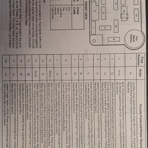
Using Relays To Wiring Off Road Lights And Accessories
Whenever wiring off road lights, it's important to add a relay to the wiring. Failure to do so would cause excessive heat in the wiring and switch and create a risk of fire. This is caused by the amount of power being drawn by the high output lights or accessories. A relay works by using a switch to run 12 volts to the relay. The relay acts as an electrical switch that activates and draws power straight from a good fused battery connection and sends it to the lights or accessory. The power actually going to the switch never gets routed to the lights. Generally you'll have a larger gauge wire going to the lights than to the switch because the lights pull much greater power.
Why do I want to use a relay and do I really need to? Anytime you want to switch a device which draws more current than is provided by an output of a switch or component you'll need to use a relay. The coil of an SPDT relay that we most commonly use draws very little current (less than 200 milliamps) and the amount of current that you can pass through a relay's common, normally closed, and normally open contacts will handle up to 30 or 40 amps. This allows you to switch devices such as headlights, parking lights, horns, etc., with low amperage outputs such as those found on keyless entry and alarm systems, and other components. In some cases you may need to switch multiple things at the same time using one output. A single output connected to multiple relays will allow you to open continuity and/or close continuity simultaneously on multiple wires.
SPDT Relay: (Single Pole Double Throw Relay) an electromagnetic switch, consist of a coil (terminals 85 & 86), 1 common terminal (30), 1 normally closed terminal (87a), and one normally open terminal (87).
When the coil of the relay is at rest (not energized), the common terminal (30) and the normally closed terminal (87a) have continuity. When the coil is energized, the common terminal (30) and the normally open terminal (87) have continuity.
This relay is similar to a SPST, but pin 30 is switched to either output pin 87A or pin 87. Pin 87A is connected in the unpowered state.
SPST Relay: (Single Pole Single Throw Relay) an electromagnetic switch, consist of a coil (terminals 85 & 86), 1 common terminal (30), and one normally open terminal (87). It does not have a normally closed terminal like the SPDT relay, but may be used in place of SPDT relays in all diagrams shown on this site where terminal 87a is not used.
When +12V is applied between pins 85 and 86 the coil becomes a magnet which pulls the lever down making a connection between pins 30 and 87.
The relay above is a SPST relay with dual outputs. These are getting harder to find.
This is a SPDT (Single Pole Double Throw) Relay
This is a SPST (Single Pole Single Throw) Relay
Using the relay diagram above, you can see that you can run a fused wire from your fuse block (Accessory jack) to a toggle switch at the dash. The wire coming from the switch would go to #86 on the relay. A heavier gauge (At least 12 Ga.) wire with a fuse would come off the battery and go to #30. #85 would be sent to a good ground, and #87 would go to you accessory or light. Most companies offer wiring kits with their products, and If your not familiar with wiring accessories then you should buy the wiring kit. Some even include the kit with the product. Most of us are cheap by nature and always looking for low-buck-do-it-yourself upgrades. That's why you read this page. Keep this wiring in mind if you pick up (2) 100 watt KC Highlites and want to bolt them on. Relays can be found by the light and electrical part of the automotive sections. They're real cheap and should never be overlooked. If you have any doubt about how much power an accessory will pull then add a relay.
Here is some useful information on wire:
The first thing you have to do is determine the current you have to carry. For DC circuits, that's relatively easy. Some equipment on a car is rated directly in current draw. Auxiliary fans, fuel pumps and things like that are rated in current draw - Amps. Some equipment is rated in Watts - mostly the lighting equipment. The power requirement in Watts will be printed right on the bulb or stamped in the base. To come up with amps use one of the formulas shown.
Current in Amps = Watts/Volts
Current in Amps = Volts/Resistance (Ohms)
Current in Amps = Square Root of (Watts/Ohms)
Watts = Amps x Volts
Volts = Watts/Amps
In an automotive electrical system, these formulas are easier since a constant of 12V is always present.
Let's calculate for a typical 100 watt driving light - the power required is 100 Watts and the voltage is 12 Volts - so the current requirement is 100 Watts/12 Volts = 8.33 Amps.
Let's assume you have to run a wire 6 feet from a relay to the lamp and look at this chart.
Gauge 1 2 4 6 8 10
20 106 53 26 17 13
18 150 75 37 25 18 15
16 224 112 56 37 28 22
14 362 181 90 60 45 36
12 572 286 143 95 71 57
10 908 454 227 151 113 90
8 1452 726 363 241 181 145
6 2342 1171 585 390 292 234
4 3702 1851 925 616 462 370
2 6060 3030 1515 1009 757 606
1 7692 3845 1923 1280 961 769
0 9708 4854 2427 1616 1213 970
Using the 10 ft. length column you'll find that you can run 15 Amps on 10 feet of 18 AWG with only ½ Volt drop. Go to the next size larger for safety margin and you're at 16 AWG.
Now in reality, you have to balance the mathematical results with mechanical reliability and efficiency. For lighting, the rated output is figured at 13.5 volts, not 12 volts. With the 0.5 volt drop shown in the chart, you have 13.0 volts available at the lamp - and at that 95% rated voltage, you are only going to get 80% of the rated output - or the equivalent of 80 watts from a 100 watt lamp.
In the example you would go to 14 AWG as the wire and connectors are physically stronger, easier to work with, and there's no voltage drop. I personally won't wire lights with anything less than 12 AWG. 14, 12 and 10 AWG is what you should be using in your truck. Those three and crimp-on connectors are readily available just about anywhere. And except for primary circuits, those three sizes will cover just about anything you want to wire in a truck with an adequate safety margin.
HERE THE LINK