- Joined
- Feb 22, 2018
- Messages
- 30
- Reaction score
- 2
- Points
- 0
- Location
- Baltimore
- Vehicle Year
- 1999
- Make / Model
- Ford
- Engine Size
- V6 3.0 FFV
- Transmission
- Automatic
- My credo
- You are what you do when it counts
Original Poster: ForTheLoveOfMonkeys
Difficulty: 7 out of 10
Time to install:
With air/power tools & dedicated workspace - 8-12hrs
With hand tools & little experience - Just take your time... 16-20hrs
Disclaimer: The Ranger Station.com, The Ranger Station.com Staff, nor the original poster are responsible for you doing this modification to your vehicle. By doing this modification and following this how-to you, the installer, take full responsibility if anything is damaged or messed up.
Brief Explanation:
Long time lurker, first time poster. I wanted to contribute given that I've learned a lot from the many knowledgeable posters here.
I recently had to change the head gasket on my beloved 99 Ranger. Browsing here I didn't see any particularly detailed how-to guides and saw many posts with questions & answers about various parts of the process. So I decided to create my own walk-through guide that compiled all of the necessary steps, tools, and torque specs along with a couple of helpful tips I uncovered along the way. I created it in Excel so please excuse any formatting issues, but I welcome constructive critique and new knowledge and would be happy to send the original excel file to any who would ask.
Tools Needed:
8mm Socket
10mm Socket
13mm Socket
15mm Socket
17mm Socket
T-50 Torx Socket
Calibrated Torque Wrench ranging from high lbs-in to roughly 75 lbs-ft
Torque Angle Guide or a white marker & protractor at least
Assorted long screwdrivers
Pliers
Lint-free towels
Patience
Parts Needed:
Replacement Gasket Set - I used FEL-PRO HS9902PT3
Cylinder Head Bolts - 16 make sure they're new
Cylinder Heads - Optional depending on your situation
Sub-System/Upper Intake Manifold Disassembly
1 Disconnect Battery
First thing
1a Discharge Fuel Pressure
1b Remove Hood
Optional, but recommended to give you more room.
2 Remove Air Intake Hose
3 Drain Radiator - Thoroughly
Remove Radiator suggested…. Not necessary
4 Remove Clutch Fan
5 Remove Serpentine Belt
6 Remove Water Pump Pulley
Not required but more space can be helpful removing hoses & cables
6a Remove Tensioner Pulley
15mm, clears space
7 Remove Radiator Hoses
7a Remove Upper Radiator Hose from Thermostat Housing
7b Remove Lower Radiator Hose from Thermostat Housing
8 Remove Throttle Cable & Cruise Control Cable
9 Disconnect Throttle from Throttle Body
2 Bolts
10 Disconnect Vacuum Line to EGR & Accompanying Vac Line
11 Remove Intake Coolant Hoses - To UIM
Label Left & Right from grill side
12 Remove Intake Vacuum Hoses - To UIM
Label Left & Right from grill side
13 Disconnect Intake Vacuum Sensor - To UIM
Suggested if cleaning Manifold
14 Disconnect Alternator Electrical Connections
3 cables, large and small and rear
15 Remove EGR
2 bolts side, one nut bottom
16 Remove Brake Booster Line
Rear of UIM, hose clamp
17 Remove Electrical Connector on Rear of UIM
Find the name for this
18 Remove Spark Plug Wires
19 Remove Ignition Coil Pack Connector
3 Bolts, several components attached
20 Remove Ignition Coil Pack
6 Bolts
20a Disconnect Vacuum Lines from beneath UIM
Left and Right from Driver Side and PCV Hose
21 Remove Top UIM
6 Bolts, note placement
Valve Cover Removal
22 Remove Alternator
3 Bolts, one nut in back, several connectors
23 Remove Alternator Bracket - Nut Holds AC Line
3 Bolts - facing grill - Partially blocked by AC Bracket
24 Remove Heater Hoses
Left and Right from Driver Side
25 Disconnect Temperature Sending Unit
26 Disconnect Fuel Injector Electrical Plugs
27 Disconnect Crank Position Sensor
28 Move Harnesses away from Engine
29 Disconnect Power Steering Pump Connector
Top of AC Bracket
30 Disconnect AC Compressor Unit
Gently, avoid damaging ac hoses - 4 or 5 bolts, 3 Front
31 Move and Secure AC Compressor Unit
Only needs to move a little forward, just to remove from CH/Block
32 Loosen Bolts Securing Fuel Rail
2 bolts on each side of fuel rail - 4 total
STOP - Clean Work Area as much as possible before continuing, vacuuming suggested
33 Carefully disengage fuel injectors
Press fit, plastic, be gentle they're expensive
34 Leaving fuel rail assembled, move to front of engine bay
Wrap in trash bag to protect and reduce fuel smell
35 Remove Valve Cover bolts from Cylinder Heads
8 bolts per head, 8mm possibly, deep socket needed
36 Remove Valve Covers to expose Cylinder Heads
Lower Intake Manifold Removal
37 Remove LIM Bolts - Torx
8 total, T-50
38 Remove LIM from CH
Lifts straight up, worth vacuuming here to avoid debris
38a Remove T-stat & housing before final removal
Suggested to replace t-stat, it's likely compromised & they're cheap
39 Remove Bolts from CH attaching Exhaust Manifold
6 total - 13mm, deep socket, bring rust buster these are infamous
Cylinder Head Removal
40 Disconnect bolts from rocker arms
12 total bolts - Keep In Order
41 Remove rocker arms from push rods
12 rocker arms - Keep In Order
42 Remove Push rods
12 push rods - Keep In Order
43 Remove Head Bolts
16 Bolts - DO NOT REUSE FOR REASSEMBLY
44 At this point carefully lift CHs away from Block
They are aluminum, be gentle in handling & storing them
45 Heads should be inspected for warps and cracking
Likely you'll be sending out to machine shop if not swapping for new
46 Coat piston walls with wd-40 or similar to prevent flash rusting
REASSEMBLY
Head Gasket Installation
Authors Notes: Any monkey with a wrench could get this far, so congrats from one ape to another. From here on out make sure everything you do has your full attention, this is where you cannot afford to fudge things, "close enough" is just not good enough. Everything you install will be critical so plan your moves ahead of time and proceed methodically and carefully, you'll thank yourself afterwards. If you feel like you messed something up it's probably better to start that part over rather than moving on and be unsure. You will sleep better if you can completely convince yourself of each step's success before installing the next part. Nothing is so torturous as getting it all back together and then having that nagging worry about whether you torqued that last head bolt enough or not right when you're ready to turn the key.
1 Thoroughly clean all mating surfaces, block, head, gasket
1a Plug channels
Tips: Rags, barbasol, etc. Stop debris from clogging
1b Use plastic razor blade to remove bulk gasket material
Do not use steel on aluminum, cannot stress this enough
1c Apply gasket remover
Specialty solution, acetone, or gasoline typically
1d Use lint free cloth to wipe away excess gasket material microfiber cloths are cheap and easily obtainable
1e Repeat process until surface is clean
2 Use milled straight edge & slip gauge to assess mating surfaces
typical tolerances are 0.002" of clearance - flatness
2a When Mating surfaces are satisfactory proceed
3 Clear Holes & Channels
clear any debris - you used a HG sealant like Bar's didn’t you? Don't worry, we all did once. Some twice. Some of us took longer to learn.
3a Apply Compressed air to all bolt holes and channels
3b Use thread chaser to clear all bolt holes
3c Apply Compressed air to all bolt holes and channels
final time - vacuum also recommended
4 Clear & Prep Piston Holes
4a Vacuum Piston Holes
4b Degrease Piston Holes
Use acetone or gasoline to remove WD40 or other residues
4c Use clean rag to lightly coat Piston Holes with motor oil prevents 'dry firing' during initial startup
5 Ensure mating surface is degreased with solvent
acetone or gasoline
6 Install spark plugs and grounding cable, etc
beats doing it while installed on truck though still doable
7 Mate Gasket to Cylinder Head
Make sure to follow directions for head gasket
8 Place long drinking straws into Block bolt holes
This is to help align the cylinder head with minimal scuffing
9 Install Cylinder Head to Block using straws as guides Ensure that the Cylinder Head is properly seated, you'll know
10 Head Bolt Installation
10a Apply light coating of grease to surface where bolt meets Head
prevents binding
10b If a bolt passes through coolant passage, apply gasket sealer
recommended you replicate on all bolts - torque symmetry
10c If no bolts pass through coolant, apply light coating of oil
avoid drips or runs, smooth light coating
10d Install Head Bolts by hand
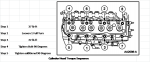
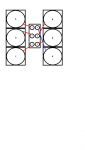
10e Follow Torquing Sequence
Smooth motions, angle gauge highly suggested
11 Cylinder Head & Gasket now installed
Pray you did everything correctly or you'll be here again
Lower Intake Manifold Installation
12 Reinstall Exhaust Manifolds - New Gaskets
These can be a pain to align, may want to disconnect from Y pipe
13 Ensure mating surfaces are clean and true
14 Install two bolts loosely to set gasket upon
15 bolt down Exhaust Manifolds, torque sequence
6 bolts per side
16 Reinstall rods & rocker arms
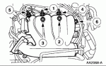
Hopefully you kept them in sequence - 12 bolts & rods
Rocker Arms Torque: Stage 1: 5-10 lb-ft | Stage 2: 20-28 lb-ft
16a Leftmost & rearmost rod installed after LIM
goes through the LIM, can't put it down over
16b use assembly lube or motor oil to prime rod ends
17 Remove old silicone/RTV from mating surfaces
Again, plastic razor blade, gasket remover or strong solvent
18 Align new intake manifold gaskets to heads
Tip: a dab of RTV or adhesive can maintain positioning
19 Lower the LIM straight down into place
helps avoid misaligning gaskets
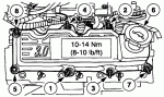
20 Bolt down following proper torquing sequence
6 bolts
21 Apply RTV black or red to mating gaps between LIM & CH
avoid excess getting into valley
22 Install last rod & rocker arm
22a Bolt down rods & rockers
Ensure they're aligned and torque down
Valve Cover Installation
23 Apply New Gaskets
Make sure they're pressed fit into place, no lube
24 Replace valve cover seals around bolts
most kits include these
25 Clean Surfaces
gentle solvent and plastic razor on plastic cover
26 RTV at mating surfaces
time sensitive, do one side at a time if unsure
27 Bolt down, follow torque sequence
8 bolts per cover
Upper Intake Manifold Reinstallation
28 Install Fuel rail and injectors
28a replace o-rings on bottom of injectors
28b press each injector firmly into appropriate place
they lightly click, you feel more than hear it. If loud, something broke
28c install fuel rail bolts
4 of them
28d good time to place connectors back on injectors
better than fighting to do it later, electrical cabling goes on studs
29 Optional, but I used this time to start connecting electrical connectors to sub-systems
30 Install removed accessories, vacuum lines, and cabling to UIM
Easier to do before installing UIM like bracket & PCV hose
29 Align and install new plenum gasket on LIM
29a place UIM onto gasket and LIM
29b lightly tighten bolts by hand to hold in place
30 Tighten down following torque procedure
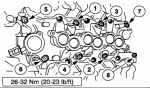
Upper Intake Manifold Torque: Stage 1 - 14 lb-ft | Stage 2 - 18 lb-ft
31 Install Throttle Body
32 Reattach Rear cabling bracket
32a Put the cruise control cable & big connector back into place
finally, for me these things were in the way the whole time
33 Re-install EGR using new gasket
tip: Install bottom nut then lever into alignment with UIM
34 Have a beer or two.
Reward yourself and take a break, you'll need it at this point
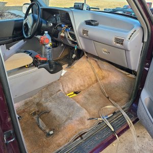
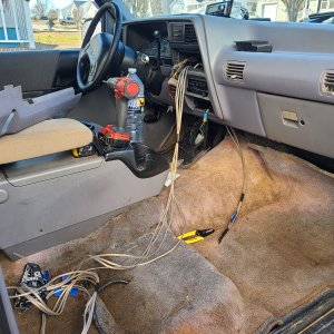
My original guide continues back up to the sub-system reassembly and is a little more comprehensive but at this point you're hopefully back into familiar territory. Please don't hesitate to let me know if you have a better way to do something I've posted or if you've got questions.
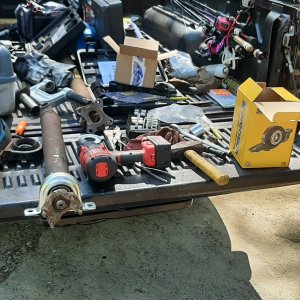
Meantime I'll leave one final useful image:
Happy Wrench Slinging and thanks for all the useful advice, most of you didn't even know you were contributing to this guide!
-ForTheLoveOfMonkeys
Difficulty: 7 out of 10
Time to install:
With air/power tools & dedicated workspace - 8-12hrs
With hand tools & little experience - Just take your time... 16-20hrs
Disclaimer: The Ranger Station.com, The Ranger Station.com Staff, nor the original poster are responsible for you doing this modification to your vehicle. By doing this modification and following this how-to you, the installer, take full responsibility if anything is damaged or messed up.
Brief Explanation:
Long time lurker, first time poster. I wanted to contribute given that I've learned a lot from the many knowledgeable posters here.
I recently had to change the head gasket on my beloved 99 Ranger. Browsing here I didn't see any particularly detailed how-to guides and saw many posts with questions & answers about various parts of the process. So I decided to create my own walk-through guide that compiled all of the necessary steps, tools, and torque specs along with a couple of helpful tips I uncovered along the way. I created it in Excel so please excuse any formatting issues, but I welcome constructive critique and new knowledge and would be happy to send the original excel file to any who would ask.
Tools Needed:
8mm Socket
10mm Socket
13mm Socket
15mm Socket
17mm Socket
T-50 Torx Socket
Calibrated Torque Wrench ranging from high lbs-in to roughly 75 lbs-ft
Torque Angle Guide or a white marker & protractor at least
Assorted long screwdrivers
Pliers
Lint-free towels
Patience
Parts Needed:
Replacement Gasket Set - I used FEL-PRO HS9902PT3
Cylinder Head Bolts - 16 make sure they're new
Cylinder Heads - Optional depending on your situation
Sub-System/Upper Intake Manifold Disassembly
1 Disconnect Battery
First thing
1a Discharge Fuel Pressure
1b Remove Hood
Optional, but recommended to give you more room.
2 Remove Air Intake Hose
3 Drain Radiator - Thoroughly
Remove Radiator suggested…. Not necessary
4 Remove Clutch Fan
5 Remove Serpentine Belt
6 Remove Water Pump Pulley
Not required but more space can be helpful removing hoses & cables
6a Remove Tensioner Pulley
15mm, clears space
7 Remove Radiator Hoses
7a Remove Upper Radiator Hose from Thermostat Housing
7b Remove Lower Radiator Hose from Thermostat Housing
8 Remove Throttle Cable & Cruise Control Cable
9 Disconnect Throttle from Throttle Body
2 Bolts
10 Disconnect Vacuum Line to EGR & Accompanying Vac Line
11 Remove Intake Coolant Hoses - To UIM
Label Left & Right from grill side
12 Remove Intake Vacuum Hoses - To UIM
Label Left & Right from grill side
13 Disconnect Intake Vacuum Sensor - To UIM
Suggested if cleaning Manifold
14 Disconnect Alternator Electrical Connections
3 cables, large and small and rear
15 Remove EGR
2 bolts side, one nut bottom
16 Remove Brake Booster Line
Rear of UIM, hose clamp
17 Remove Electrical Connector on Rear of UIM
Find the name for this
18 Remove Spark Plug Wires
19 Remove Ignition Coil Pack Connector
3 Bolts, several components attached
20 Remove Ignition Coil Pack
6 Bolts
20a Disconnect Vacuum Lines from beneath UIM
Left and Right from Driver Side and PCV Hose
21 Remove Top UIM
6 Bolts, note placement
Valve Cover Removal
22 Remove Alternator
3 Bolts, one nut in back, several connectors
23 Remove Alternator Bracket - Nut Holds AC Line
3 Bolts - facing grill - Partially blocked by AC Bracket
24 Remove Heater Hoses
Left and Right from Driver Side
25 Disconnect Temperature Sending Unit
26 Disconnect Fuel Injector Electrical Plugs
27 Disconnect Crank Position Sensor
28 Move Harnesses away from Engine
29 Disconnect Power Steering Pump Connector
Top of AC Bracket
30 Disconnect AC Compressor Unit
Gently, avoid damaging ac hoses - 4 or 5 bolts, 3 Front
31 Move and Secure AC Compressor Unit
Only needs to move a little forward, just to remove from CH/Block
32 Loosen Bolts Securing Fuel Rail
2 bolts on each side of fuel rail - 4 total
STOP - Clean Work Area as much as possible before continuing, vacuuming suggested
33 Carefully disengage fuel injectors
Press fit, plastic, be gentle they're expensive
34 Leaving fuel rail assembled, move to front of engine bay
Wrap in trash bag to protect and reduce fuel smell
35 Remove Valve Cover bolts from Cylinder Heads
8 bolts per head, 8mm possibly, deep socket needed
36 Remove Valve Covers to expose Cylinder Heads
Lower Intake Manifold Removal
37 Remove LIM Bolts - Torx
8 total, T-50
38 Remove LIM from CH
Lifts straight up, worth vacuuming here to avoid debris
38a Remove T-stat & housing before final removal
Suggested to replace t-stat, it's likely compromised & they're cheap
39 Remove Bolts from CH attaching Exhaust Manifold
6 total - 13mm, deep socket, bring rust buster these are infamous
Cylinder Head Removal
40 Disconnect bolts from rocker arms
12 total bolts - Keep In Order
41 Remove rocker arms from push rods
12 rocker arms - Keep In Order
42 Remove Push rods
12 push rods - Keep In Order
43 Remove Head Bolts
16 Bolts - DO NOT REUSE FOR REASSEMBLY
44 At this point carefully lift CHs away from Block
They are aluminum, be gentle in handling & storing them
45 Heads should be inspected for warps and cracking
Likely you'll be sending out to machine shop if not swapping for new
46 Coat piston walls with wd-40 or similar to prevent flash rusting
REASSEMBLY
Head Gasket Installation
Authors Notes: Any monkey with a wrench could get this far, so congrats from one ape to another. From here on out make sure everything you do has your full attention, this is where you cannot afford to fudge things, "close enough" is just not good enough. Everything you install will be critical so plan your moves ahead of time and proceed methodically and carefully, you'll thank yourself afterwards. If you feel like you messed something up it's probably better to start that part over rather than moving on and be unsure. You will sleep better if you can completely convince yourself of each step's success before installing the next part. Nothing is so torturous as getting it all back together and then having that nagging worry about whether you torqued that last head bolt enough or not right when you're ready to turn the key.
1 Thoroughly clean all mating surfaces, block, head, gasket
1a Plug channels
Tips: Rags, barbasol, etc. Stop debris from clogging
1b Use plastic razor blade to remove bulk gasket material
Do not use steel on aluminum, cannot stress this enough
1c Apply gasket remover
Specialty solution, acetone, or gasoline typically
1d Use lint free cloth to wipe away excess gasket material microfiber cloths are cheap and easily obtainable
1e Repeat process until surface is clean
2 Use milled straight edge & slip gauge to assess mating surfaces
typical tolerances are 0.002" of clearance - flatness
2a When Mating surfaces are satisfactory proceed
3 Clear Holes & Channels
clear any debris - you used a HG sealant like Bar's didn’t you? Don't worry, we all did once. Some twice. Some of us took longer to learn.
3a Apply Compressed air to all bolt holes and channels
3b Use thread chaser to clear all bolt holes
3c Apply Compressed air to all bolt holes and channels
final time - vacuum also recommended
4 Clear & Prep Piston Holes
4a Vacuum Piston Holes
4b Degrease Piston Holes
Use acetone or gasoline to remove WD40 or other residues
4c Use clean rag to lightly coat Piston Holes with motor oil prevents 'dry firing' during initial startup
5 Ensure mating surface is degreased with solvent
acetone or gasoline
6 Install spark plugs and grounding cable, etc
beats doing it while installed on truck though still doable
7 Mate Gasket to Cylinder Head
Make sure to follow directions for head gasket
8 Place long drinking straws into Block bolt holes
This is to help align the cylinder head with minimal scuffing
9 Install Cylinder Head to Block using straws as guides Ensure that the Cylinder Head is properly seated, you'll know
10 Head Bolt Installation
10a Apply light coating of grease to surface where bolt meets Head
prevents binding
10b If a bolt passes through coolant passage, apply gasket sealer
recommended you replicate on all bolts - torque symmetry
10c If no bolts pass through coolant, apply light coating of oil
avoid drips or runs, smooth light coating
10d Install Head Bolts by hand
10e Follow Torquing Sequence
Smooth motions, angle gauge highly suggested
11 Cylinder Head & Gasket now installed
Pray you did everything correctly or you'll be here again
Lower Intake Manifold Installation
12 Reinstall Exhaust Manifolds - New Gaskets
These can be a pain to align, may want to disconnect from Y pipe
13 Ensure mating surfaces are clean and true
14 Install two bolts loosely to set gasket upon
15 bolt down Exhaust Manifolds, torque sequence
6 bolts per side
16 Reinstall rods & rocker arms
Hopefully you kept them in sequence - 12 bolts & rods
Rocker Arms Torque: Stage 1: 5-10 lb-ft | Stage 2: 20-28 lb-ft
16a Leftmost & rearmost rod installed after LIM
goes through the LIM, can't put it down over
16b use assembly lube or motor oil to prime rod ends
17 Remove old silicone/RTV from mating surfaces
Again, plastic razor blade, gasket remover or strong solvent
18 Align new intake manifold gaskets to heads
Tip: a dab of RTV or adhesive can maintain positioning
19 Lower the LIM straight down into place
helps avoid misaligning gaskets
20 Bolt down following proper torquing sequence
6 bolts
21 Apply RTV black or red to mating gaps between LIM & CH
avoid excess getting into valley
22 Install last rod & rocker arm
22a Bolt down rods & rockers
Ensure they're aligned and torque down
Valve Cover Installation
23 Apply New Gaskets
Make sure they're pressed fit into place, no lube
24 Replace valve cover seals around bolts
most kits include these
25 Clean Surfaces
gentle solvent and plastic razor on plastic cover
26 RTV at mating surfaces
time sensitive, do one side at a time if unsure
27 Bolt down, follow torque sequence
8 bolts per cover
Upper Intake Manifold Reinstallation
28 Install Fuel rail and injectors
28a replace o-rings on bottom of injectors
28b press each injector firmly into appropriate place
they lightly click, you feel more than hear it. If loud, something broke
28c install fuel rail bolts
4 of them
28d good time to place connectors back on injectors
better than fighting to do it later, electrical cabling goes on studs
29 Optional, but I used this time to start connecting electrical connectors to sub-systems
30 Install removed accessories, vacuum lines, and cabling to UIM
Easier to do before installing UIM like bracket & PCV hose
29 Align and install new plenum gasket on LIM
29a place UIM onto gasket and LIM
29b lightly tighten bolts by hand to hold in place
30 Tighten down following torque procedure
Upper Intake Manifold Torque: Stage 1 - 14 lb-ft | Stage 2 - 18 lb-ft
31 Install Throttle Body
32 Reattach Rear cabling bracket
32a Put the cruise control cable & big connector back into place
finally, for me these things were in the way the whole time
33 Re-install EGR using new gasket
tip: Install bottom nut then lever into alignment with UIM
34 Have a beer or two.
Reward yourself and take a break, you'll need it at this point
My original guide continues back up to the sub-system reassembly and is a little more comprehensive but at this point you're hopefully back into familiar territory. Please don't hesitate to let me know if you have a better way to do something I've posted or if you've got questions.
Meantime I'll leave one final useful image:
Happy Wrench Slinging and thanks for all the useful advice, most of you didn't even know you were contributing to this guide!
-ForTheLoveOfMonkeys
Last edited: