• Welcome Visitor! Please take a few seconds and Register for our forum. Even if you don't want to post, you can still 'Like' and react to posts.

Reverse Lights Only Not Working Ranger '97 Fuse Pop When Put In Reverse


RangerNeophyte

New Member
Joined
Apr 22, 2015
Messages
19
Reaction score
1
Points
0
Vehicle Year
1997
Make / Model
Ford
Transmission
Manual
Year:1997
R-1 5 speed


Before I begin let me start by saying I've done some research in this website and after 4 pages I've come up empty for an answer.

Research done:

The rod that pushes into the reverse lights switch is still in my transmission as was the problem found in this thread

I did the trouble shoot from this thread by UrbanRedneckKid. I'll elaborate in the narrative section.

I watched this video about fuse blowing similar to mine, but this is for an automatic. Mine's a manual.

I just changed the transmission fluid. So that should be an issue anymore as Colin pointed out at the end of this thread.

It's just my reverse lights that keep blowing the fuse. My turn signal lights are fine. As is the problem in this thread.

My specific problem:


Every time I put my manual transmission truck in reverse the 10v fuse blows. It does not blow before I put it in reverse. The car can be off and it still blows when put in reverse.

I have tried:

1) Removing the reverse light bulbs from their housing. Put it into reverse. Fuse blew.

2) Went to the junk yard picked up 4 different reverse switcher - surely all of them can't be bad - I replace the original one with each of them. Each time I put it into reverse. Fuse blew.

3) I tried running the car and using a multimeter on the "continuity," "D/C," and "Ohms" setting, while grounding off on the body of the car. I put the red multimeter end in each of the two holes and did not get a reading.

4) I also tried plugging the reverse switch into the wire harness and pressed, with my fingers, the ball on the end to see if the lights would come on. No luck, the backup lights did not come on.

Conclusion:

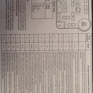
I think I've narrowed it down to something in the wiring that plugs into the reverse switch, but I really don't know where to go from here. I have located several wiring diagrams, none of them show the configuration of the reverse lights from beginning to end. If they do show it from beginning to end, I don't exactly know where the wire is located. Maybe I need to remove the kick panel, radio, or dash covering, etc... or maybe not.

Questions:

Should I trace the wire itself from the fuse panel to the revers light switch by removing the kick panel under the steering wheel, etc?

Did I use the multimetere correctly by grounding out on the body, and placing the red wires set on "D/C" in the hot wire side, and "Ohms" in the grounding side?

If I push the ball into the reverse light switch manually with my finger should the reverse lights turn on?

Any other thoughts about what might be going on?

I'm beginning to think maybe there is a wire that got fried or exposed, but I don't know where the wire comes from to the reverse lights switch to check.


I know this is a lot, but maybe after I get this resolved someone else can use the info.:D

Cheers!
 
Last edited:


martin

New Member
Joined
Aug 6, 2007
Messages
3,218
Reaction score
26
Points
0
Age
77
Location
St Bruno, Quebec
Vehicle Year
1984
1991
Make / Model
ford
Transmission
Manual
please clarify your statement "The car can be off and it still blows when put in reverse." is the ignition switch completely off or just motor not running. I believe there should not be power on the line when the ignition is in the off position.
 

RangerNeophyte

New Member
Joined
Apr 22, 2015
Messages
19
Reaction score
1
Points
0
Vehicle Year
1997
Make / Model
Ford
Transmission
Manual
please clarify your statement "The car can be off and it still blows when put in reverse." is the ignition switch completely off or just motor not running. I believe there should not be power on the line when the ignition is in the off position.
Right, sorry for the late response. I can't actually say for sure. I think it blows whether the ignition is turned on without engine running or completely off, but I'll post later today or tomorrow for confirmation.

Really thankful for any help you might be able to provide.
 
Last edited:

griz700rocket

New Member
Joined
Oct 6, 2014
Messages
126
Reaction score
0
Points
0
Vehicle Year
1996
Make / Model
Ford
Engine Size
4.0
Transmission
Manual
On my friends 92 ranger with a manual trans the wiring harness had came loose toward the front of the trans. It then got into the exhaust manifold where it melted through and grounded out. Be worth checking.
 

hoosier1104

I'm Awesome!
Supporting Member
U.S. Military - Veteran
V8 Engine Swap
MTOTM Winner
TRS Banner 2010-2011
TRS Banner 2012-2015
Joined
Jul 17, 2009
Messages
5,123
Reaction score
104
Points
0
Location
Camby, IN
Vehicle Year
1999
Make / Model
Ford
Engine Size
302 based goodness
Transmission
Automatic
My credo
Work hard and play harder
Sounds like you got a short in the reverse light circuit.
 

cvar

Member
Joined
Apr 27, 2012
Messages
588
Reaction score
19
Points
18
Vehicle Year
1997
Make / Model
Mazda
Engine Size
4.0L V6
Transmission
Automatic
Yes, you have a short circuit somewhere along circuit #140, between the Backup Lamp Switch and the tail lamps.

See http://imgur.com/a/u8bks <== CLICK for wiring details.

Notice the 1st and 2nd pictures that show the FULL path. I gave you all the connectors along the entire path, along with the location of each connector, and each of their pinouts. That should give you all the info you need to hunt down your short circuit.

Somewhere along that path, the #140 BK/PK wire is shorted to ground. Oops! That means 12V power coming from your BACKUP_LAMP_SWITCH is being shorted (ie, wrongly diverted) to ground WITHOUT passing through any sort of resistive load (ie. a lamp), and therefore, it blows a fuse. Only the lamp itself is what limits the amount of current being drawn thru that fuse (ie, preventing fuse blowout). A short circuit that wrongly bypasses that lamp means you instantly draw WAY too much power down that wire from that fuse. BAM!

A bare wire #140 touching the frame (ie, worn plastic wire insulation) would do that.

You need to use your OHM meter to detect the improper grounding of circuit #140 at each of those connectors, at the appropriate pin #. Disconnect each of those connectors, one by one, and test the pin for continuity with ground (ie, your frame). Keep disconnecting those connectors, 1 by 1, working from your BACKUP_LAMP_SWITCH towards the tails (or vice versa) until you find the smallest section of wire that is shorted to ground. Then follow the actual wire along that portion, to find the problem. Then fix the insulation or replace that small section of wire.

A continuity tester (ie, OHM meter) will work perfectly for this.

WARNING: NEVER apply any voltage to a circuit when using an OHM meter. That would destroy your meter.

Good luck.
 
Last edited:

RangerNeophyte

New Member
Joined
Apr 22, 2015
Messages
19
Reaction score
1
Points
0
Vehicle Year
1997
Make / Model
Ford
Transmission
Manual
please clarify your statement "The car can be off and it still blows when put in reverse." is the ignition switch completely off or just motor not running. I believe there should not be power on the line when the ignition is in the off position.
As promised: You're right, when the ignition is in the off position the fuse does not blow. As soon as I turn the key over, it blows.

On my friends 92 ranger with a manual trans the wiring harness had came loose toward the front of the trans. It then got into the exhaust manifold where it melted through and grounded out. Be worth checking.
I'll check this out. Thanks.

Yes, you have a short circuit somewhere along circuit #140, between the Backup Lamp Switch and the tail lamps.

See http://imgur.com/a/u8bks <== CLICK for wiring details.

Notice the 1st and 2nd pictures that show the FULL path. I gave you all the connectors along the entire path, along with the location of each connector, and each of their pinouts. That should give you all the info you need to hunt down your short circuit.

Somewhere along that path, the #140 BK/PK wire is shorted to ground. Oops! That means 12V power coming from your BACKUP_LAMP_SWITCH is being shorted (ie, wrongly diverted) to ground WITHOUT passing through any sort of resistive load (ie. a lamp), and therefore, it blows a fuse. Only the lamp itself is what limits the amount of current being drawn thru that fuse (ie, preventing fuse blowout). A short circuit that wrongly bypasses that lamp means you instantly draw WAY too much power down that wire from that fuse. BAM!

A bare wire #140 touching the frame (ie, worn plastic wire insulation) would do that.

You need to use your OHM meter to detect the improper grounding of circuit #140 at each of those connectors, at the appropriate pin #. Disconnect each of those connectors, one by one, and test the pin for continuity with ground (ie, your frame). Keep disconnecting those connectors, 1 by 1, working from your BACKUP_LAMP_SWITCH towards the tails (or vice versa) until you find the smallest section of wire that is shorted to ground. Then follow the actual wire along that portion, to find the problem. Then fix the insulation or replace that small section of wire.

A continuity tester (ie, OHM meter) will work perfectly for this.

WARNING: NEVER apply any voltage to a circuit when using an OHM meter. That would destroy your meter.

Good luck.
Perfect. I'm going to study this intently for the next few work days, then get out to the truck, on probably Thursday, and try my damnedest to figure it out. Man, this is great!

Also, warning noted.

This post is like a nesting doll. Each time I open a link there is even more helpful information inside.
 
Last edited:

cvar

Member
Joined
Apr 27, 2012
Messages
588
Reaction score
19
Points
18
Vehicle Year
1997
Make / Model
Mazda
Engine Size
4.0L V6
Transmission
Automatic
Watch this for how to test for continuity, using an Ohm meter:
https://www.youtube.com/watch?v=x3nqlXM6nOM

If your meter doesn't BEEP when you touch its 2 leads together, then you've got an old-style meter, but it can still be used. So instead of listening for a beep, you'd look for a LOW number close to ZERO Ohms, which indicates power is flowing out 1 lead and into the other lead of your meter (ie, you DO have continuity). Conversely, a HIGH number of Ohms means there's NO continuity between the meter's 2 leads. For OHMS, it doesn't matter which lead is red or black. The red vs. black leads only matters for measuring DC Volts (which you're NOT doing here).
 

RangerNeophyte

New Member
Joined
Apr 22, 2015
Messages
19
Reaction score
1
Points
0
Vehicle Year
1997
Make / Model
Ford
Transmission
Manual
Yes, you have a short circuit somewhere along circuit #140, between the Backup Lamp Switch and the tail lamps.

See http://imgur.com/a/u8bks <== CLICK for wiring details.

Notice the 1st and 2nd pictures that show the FULL path. I gave you all the connectors along the entire path, along with the location of each connector, and each of their pinouts. That should give you all the info you need to hunt down your short circuit.

Somewhere along that path, the #140 BK/PK wire is shorted to ground. Oops! That means 12V power coming from your BACKUP_LAMP_SWITCH is being shorted (ie, wrongly diverted) to ground WITHOUT passing through any sort of resistive load (ie. a lamp), and therefore, it blows a fuse. Only the lamp itself is what limits the amount of current being drawn thru that fuse (ie, preventing fuse blowout). A short circuit that wrongly bypasses that lamp means you instantly draw WAY too much power down that wire from that fuse. BAM!

A bare wire #140 touching the frame (ie, worn plastic wire insulation) would do that.

You need to use your OHM meter to detect the improper grounding of circuit #140 at each of those connectors, at the appropriate pin #. Disconnect each of those connectors, one by one, and test the pin for continuity with ground (ie, your frame). Keep disconnecting those connectors, 1 by 1, working from your BACKUP_LAMP_SWITCH towards the tails (or vice versa) until you find the smallest section of wire that is shorted to ground. Then follow the actual wire along that portion, to find the problem. Then fix the insulation or replace that small section of wire.

A continuity tester (ie, OHM meter) will work perfectly for this.

WARNING: NEVER apply any voltage to a circuit when using an OHM meter. That would destroy your meter.

Good luck.

Let me begin by saying that my user name is apt.

Well, I got out there yesterday and began taking apart wires step by step as you instructed. I started with the wire harness (C403) located before the splice (S403). I noticed that something was not on the diagram you gave me. There was a tow light harness between the male (C403M) and female (C403F). I decided just to take it out and continue my business. I clipped together C403M and C403F leaving out the T harness, and putting it in my cab. At this point I should have checked to see if the reverse lights were working.

Now let me say, even after testing four out of the six femal/male wire harnesses, I am still really confused on the ground/not ground dichotomy. Sometimes I would test the correct pin going toward the ground (which is toward the back up lamps at the tail), and still not get a reading on the OHM setting.

So let me get this straight, I want to ground my multimeter to the frame (black wire) and then check the correct wire with my other wire (red wire), making sure I'm testing the wire/pin heading toward the ground (G200) at the tail of the car, right? Sometimes I'd get a signal going toward the ground, but sometime neither. For example on both C403M/C403F and C1007M/C1007F I didn't get a reading. I made sure my ground coming from the multimeter was secure by touching other pins in the same wire harness. Maybe my multimeter is too weak to detect long circuits?

Anyway, I spent a solid four or five hours outside messing around with wires, and taking things apart to get at more wires. Finally after calling it a day and getting ready to play around with it again later, I figured I'd try it for ships and giggles. I threw it in reverse and sure enough... no pop! The fricking thing worked like a charm. After all that fuss I'm 99% sure it was the first thing I fixed. You know, the thing that I thought it wouldn't be.:annoyed:

Lesson learned: When you change something in the system STOP and check your work!

Thanks for all the help. I've gotten to know my truck's electrical system way better than I did two days ago.

Also, I saved your imgur link in an online archive. That way the link won't decay for future readers. Also what book do you use? I might pick it up.

Here's the link:

http://web.archive.org/web/20150508085301/http://imgur.com/a/u8bks

For anybody reading this with the same problem: It is a mystery how someone would get at C130M/C130F without lowering the transmission or lifting the engine. It is really tucked away in there. Also, C134 is behind the fuse box on the LHS firewall. There are three different wire sets back there. The one you want is on the very top. Besides those two things, the rest of them are pretty easy to get at, and exactly where Cvar has instructed. Lastly, make sure to disconnect your negative battery cable before getting too far into electrical stuff.

TL;DR Removed the towing electric T harness from between C403M and C403F, plugging the male and female directly into each other. The reverse lights worked.:headbang:
 
Last edited:

cvar

Member
Joined
Apr 27, 2012
Messages
588
Reaction score
19
Points
18
Vehicle Year
1997
Make / Model
Mazda
Engine Size
4.0L V6
Transmission
Automatic
Your OHM meter does NOT beep? Oh well, too bad. Let's use numbers instead.

How to use an ohm meter:

Touch one lead to the frame (ok, black), and the other lead (ok, red) to something else. The idea is that your meter reads almost ZERO ohms (also BEEPS) if there's a CONTINUOUS conductor (ie, metal) between the 2 leads. But it reads THOUSANDS of ohms (and NO BEEP) if there's NOT continuous metal between leads. Got it? GO or NO-GO. There's no middle area, for this test. Just all or nothing.

To test for continuity, touch the 2 leads together, and your meter should read ZERO ohms (and it BEEPS). Do the same with a short piece of wire, etc. The longer the wire, the further from ZERO, but 1000 feet of wire is still gonna be under 1 ohm. Anything in the middle (between 1 and THOUSAND ohms) is just a bad connection, so move your RED probe until you get a PROPER connection.

WARNING 1) Disconnect your battery. Touching 12V power will DESTROY your ohm meter instantly.
WARNING 2) The reverse lamps contain a wire filament that's ALSO a conductor. The diagram says 1 side of the lamp is grounded. So you need to REMOVE both lamps from the sockets BEFORE testing continuity of their common power wire. Otherwise your meter will read both (and you'll be confused by) 2 paths to ground (1 path from RED to BLACK lead) and (2nd path via either lamp to ground), so you'll get FALSE readings. Oops!

First, REMOVE the lamps. Then NO PLACE on the entire circuit 140 should be grounded. Absolutely NO continuity of that circuit wire to your frame, ANYWHERE along that wire. Your meter should read THOUSANDS ohms (and NO BEEP) for EVERY pin along the entire route, from the lamp socket C401 all the way thru to the C1012 Backup Switch . If it goes to ZERO (or BEEPS) anywhere along that path, then you found a big problem, or else your RED lead is inadvertently touching something else. Oops!

BTW, I assume your meter's internal battery is not dead (or dying).

Regarding books...

Search ebay for "1997 Ford Ranger Service Manual"

The complete set is 3 books ('97 color is maroon), and the smallest book is the Electrical (EVTM) book. A good price is usually under $50 for the complete set of 3. I posted photos from my copy of the EVTM book. FYI, I also bought a copy on CDROM, but it's garbage compared to what's in the Ford paper books. The 3 Ford books are awesome.

http://www.ebay.com/itm/1997-Ford-Ranger-Aerostar-OEM-Service-Repair-Shop-Manual-Set-W-Wiring-Book-/361288422314
 
Last edited:

RangerNeophyte

New Member
Joined
Apr 22, 2015
Messages
19
Reaction score
1
Points
0
Vehicle Year
1997
Make / Model
Ford
Transmission
Manual
Your OHM meter does NOT beep? Oh well, too bad. Let's use numbers instead.

How to use an ohm meter:

Touch one lead to the frame (ok, black), and the other lead (ok, red) to something else. The idea is that your meter reads almost ZERO ohms (also BEEPS) if there's a CONTINUOUS conductor (ie, metal) between the 2 leads. But it reads THOUSANDS of ohms (and NO BEEP) if there's NOT continuous metal between leads. Got it? GO or NO-GO. There's no middle area, for this test. Just all or nothing.

To test for continuity, touch the 2 leads together, and your meter should read ZERO ohms (and it BEEPS). Do the same with a short piece of wire, etc. The longer the wire, the further from ZERO, but 1000 feet of wire is still gonna be under 1 ohm. Anything in the middle (between 1 and THOUSAND ohms) is just a bad connection, so move your RED probe until you get a PROPER connection.

WARNING 1) Disconnect your battery. Touching 12V power will DESTROY your ohm meter instantly.
WARNING 2) The reverse lamps contain a wire filament that's ALSO a conductor. The diagram says 1 side of the lamp is grounded. So you need to REMOVE both lamps from the sockets BEFORE testing continuity of their common power wire. Otherwise your meter will read both (and you'll be confused by) 2 paths to ground (1 path from RED to BLACK lead) and (2nd path via either lamp to ground), so you'll get FALSE readings. Oops!

First, REMOVE the lamps. Then NO PLACE on the entire circuit 140 should be grounded. Absolutely NO continuity of that circuit wire to your frame, ANYWHERE along that wire. Your meter should read THOUSANDS ohms (and NO BEEP) for EVERY pin along the entire route, from the lamp socket C401 all the way thru to the C1012 Backup Switch . If it goes to ZERO (or BEEPS) anywhere along that path, then you found a big problem, or else your RED lead is inadvertently touching something else. Oops!

BTW, I assume your meter's internal battery is not dead (or dying).

Regarding books...

Search ebay for "1997 Ford Ranger Service Manual"

The complete set is 3 books ('97 color is maroon), and the smallest book is the Electrical (EVTM) book. A good price is usually under $50 for the complete set of 3. I posted photos from my copy of the EVTM book. FYI, I also bought a copy on CDROM, but it's garbage compared to what's in the Ford paper books. The 3 Ford books are awesome.

http://www.ebay.com/itm/1997-Ford-Ranger-Aerostar-OEM-Service-Repair-Shop-Manual-Set-W-Wiring-Book-/361288422314
You're the man. Okay, got it. The OHM meter was confused because I had the tail lights still in the sockets. Right, should have thought of that. Noted for next time.

Got it, disconnecting the tail lights then tracing the path back to the BACK-UP LAMPS. My OHM meter shouldn't read anything except for 1,000. If it reads ZERO then there is something wrong.

I was mistaken then to think that going from BACK-UP SWITCH to GROUND @ REAR would give me a ZERO reading. Got it.

I want 1,000 not 0.

CVAR you taught me something quite valuable. I am forever grateful. :icon_bounceblue:
 

Sponsored Ad


Sponsored Ad

Staff online

Today's birthdays

Member & Vendor Upgrades

For a small yearly donation, you can support this forum and receive a 'Supporting Member' banner, or become a 'Supporting Vendor' and promote your products here. Click the banner to find out how.

Truck of The Month


Shran
April Truck of The Month

Recently Featured

Want to see your truck here? Share your photos and details in the forum.

Follow TRS On Instagram

TRS Events

25th Anniversary Sponsors

Check Out The TRS Store


Sponsored Ad


Sponsored Ad

Sponsored Ad


Amazon Deals

Top