|
|
|
|
2.9L MAF Conversion - Detailed Procedures |
|
Revision K, 06/15/2001
By Bob Marrs, Scottsdale, AZ. (bobmarrs@aol.com) Long term view: I did this conversion in Spring of 1999. Two years later it's still running well, with no problems. Early in 2001, I rebuilt this engine, adding high compression pistons (9.8), a hot cam, ported heads, and extensive porting in lower/upper intakes. The MAF system outlined here has adapted well to all these changes. Revision Notes: Revision "A" fixed a few unclear items in first release, corrects grammar errors, adds wiring comparison chart, and expands the useful reference list at the end. Rev B fixed wiring table formats. Rev C added (6.4) information about handling air conditioning problems in some vehicles. Rev D added "IST" reference info), Rev E added Section 7, Rev F added some references, changed 4.11, as well as additional misc. wiring notes about '86/87 vehicles. Rev G added Section 8. Rev H added information regarding MAF re-calibration by Pro-Flow, setting up MAF meter after installation, and advice regarding installation of an air-fuel gauge. Rev I omitted 5.16 and 5.17, fixed a few typos, added Performance section. Rev. J fixed minor errors in wiring references. Rev K was all grammatical. Summary: The following is a step by step procedure for converting a standard speed density controlled 2.9L V6 engine to a MAF (mass airflow) controlled system. This conversion includes swapping the EEC-IV computer, adding required sensors, upgrading to higher performance injectors, adding a larger MAF meter, installing suggested air-fuel ratio monitors and MAF fine tuning tools. About Mass Air Systems: From Ford Motorsports "Remembering that engines are basically air pumps, the basic problems for an EEC-IV computer is to determine airflow for any given throttle angle and engine RPM, so it can signal appropriate fuel flow to mix with the air. The (2.9L and) 5.0L engines use two types of fuel control systems. Speed Density system -- in which airflow is INFERRED from several sensors, including measurements of engine speed, manifold pressure and air charge temperature, along with an approximation of the engines pumping characteristics. Other models use Mass Air system -- in which airflow is measured DIRECTLY with an air meter. A "hot wire" sensing element in the air intake provides an output voltage reading that is proportional to the mass of air flowing into the engine. The mass air system reduces the calculations required to control fuel flow and ignition spark advance -- while providing the versatility required for performance modifications affecting airflow and manifold vacuum. It reacts faster and more accurately to changes in airflow, and improves idle quality and overall vehicle performance. MAF conversion features continues good drive-ability when you improve performance by installing...equipment such as camshafts, high flow cylinder heads, headers, or other changes." PERFORMANCE: You should not expect any great performance gains when just switching to the MAF system from speed density (unless you already have a highly modified engine, which is not getting the proper air-fuel mixture). You WILL get greatly improved idle and low speed performance. As you build your engine, the new MAF system will be highly adaptable to changes, which affect airflow and volumetric efficiency. Prior to Starting: 1. Be sure your truck is in good running condition. Using the computer scanner, check the computer codes for any errors and resolve them. But do not bother replacing any EGR related components as these are not functional in the MAF computer. 2. Set the timing to 10 degrees according to factory procedure. 3. I REALLY suggest you install an air-fuel meter (such as Cyberdyne one noted herein) a few weeks prior to starting the actual conversion and get data off it in various operating conditions. This data will be useful in establishing a baseline of air-fuel ratios in various conditions and trouble shooting possible problems later. This is a useful tool in diagnostics. You may wish to install it even if you are not doing the MAF conversion. It's useful anytime you are changing engine components for improved performance. 4. You may wish to check your gas mileage and record it so you can make some comparisons later. 5. You may also wish to run some performance test. Something simple like checking MPH when accelerating from point to point can be of interest later. 6. Gather a good set of wiring diagrams for your EXACT year model. These will be useful to check against later. FYI, there can be minor wiring variations from year to year which are not reflected herein. 7. This conversion was done on a 1986 Bronco II, 4x4, 5 speed. Your application may have some differences. For example, the throttle body size is about 58mm on the 1986 model, and smaller in later years. List of Parts & Things Required: Note, I used many used parts. Prices are for new or used as indicated. 1. EEC-IV MAF computer. The required computer originates from a 1990 California 2.9L with a MAF set-up. This is available (rebuilt/reconditioned) from Ford (about $240 + core charge) or after-market (Pepboys or Checker Auto, $100 + core). Finding it: I called Checker Auto main warehouse out here in Arizona and found they actually had the computer in stock. It's a remanufactured unit by "Cardone". EEC-IV Computer = Checker P/N 78-4905 (manual trans version). The original Ford EEC-IV P/N is F07F 12A650-DA (manual trans version). I think the auto trans version of the computer is a -FA.
2. New MAF "Conversion Harness", #CH-6811-F, by "IST" (this is a MAF connector with four, 10 foot wires connected, a few pins to insert into the 60 pin EEC-IV computer, instructions). FYI, it's designed for a 5.0L MAF conversion. $29.95 from IST, listed in suppliers at G. below. You also need to order 3-4 extra pin connectors from them. These are additional. You need them for the 2 additional wires needed for the self-test connector.
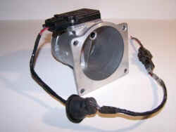
3. Used MAF meter and air hoses from an early 90's 3.8L Taurus or 5.0L Mustang. Part number is P/N F1ZF 12B579-AA. Mine was from a 1993 3.8L Taurus. $40. Also, as another source, IST advertised stock mass-air units for $60 and air-hoses for $65.
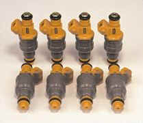
4. Rubber grommet for firewall, to fit 1/2 to 5/8" hole ($3.19 @ auto parts store for an assortment of sizes, or under $1.00 at the hardware store). 5. Four feet of 1/2" plastic wire loom ($2.99 @ auto parts store). 6. Six feet of 3/8" plastic wire loom, $2.99 (for speed sensor -- not needed if you have a sensor already on your trans). 7. 19lb injectors ($50 used). Side note, 19lb injectors will be good about 200-240hp peak. You can use 19lb (gold or orange) injectors from either a 5.0L or a 4.6L -- they are both high impedance injectors like the 2.9L stock ones.
8. 5" stainless hose clamp: $1.25 9. Misc - silicone sealant, 10-15 wire ties. 10. Upper intake manifold gasket. $8.99 11. Brass plug, 3/8". $1.29 (not needed if you do not have EGR on engine). 12. Fuel injector O-rings, 12 @ $0.50 = $6.00 (2 per injector needed). As an option there are also extreme temperature O-rings for very cold climate available from Ford. 13. Speed Sensor, Ford part # E3AZ-9E731-A, list price $25.13 (part # is the one for a manual trans without cruise control). And you need electrical connector pigtail #E4AB-14489-AA, $9.88 (also called 6790 Coil P): There are a number of different types of speed sensors. Ford can help you get the right one. There is after-market ones as well, which come with both the sensor and connector for about $35. These are only needed if you do not have an existing speed sensor. 1986 Speed sensor assembly is 9E731.
IST shows sells a speed sensor kit for $79.95. You should check into this. 14. Special tools: 1/2 or 5/8" drill bit (to match grommet size used in firewall), soldering iron, and electrical grade solder. A volt-ohm-meter is useful too. 15. MAF meter recalibration by Pro-Flow, $85 plus freight. This is not needed if you use the stock MAF meter and injectors. 16. Air-Fuel Gauge: Cyberdyne #7009, $47.50 delivered. From "Force Fuel Injection", Reference H. Key Project Steps: SECTION 1. Install MAF Meter. Send out for recalibration. SECTION 2. Wiring the MAF Meter to computer area. SECTION 3. Install & Wire Speed Sensor (if one is not already on transmission). SECTION 4. Install computer and wire everything to it. SECTION 5. Install 19lb. injectors. SECTION 6. Notes on old engine sensors SECTION 7. Air Adjuster Installation SECTION 8. Getting Going. USEFUL REFERENCES: A. MISC. DIMENSIONAL & RELATED MAF NOTES, FYI B. WIRING DIAGRAMS C. EXAMPLE OF A PIN OUT COMPARISON BY NUMBER BETWEEN AN '86/'87 SPEED DENSITY SYSTEM '90 MAF SYSTEM D. SUPPLIERS & USEFUL REFERENCES E. PINGING and MAF SECTION 1: Install MAF Meter / Send out for recalibration. Time, about 1 hour. Really Easy! The stock type 5.0L MAF meter mounts midway between the airbox and the throttle body. It does not attach to the airbox like the stock ones (and the 3.0L or 4.0L ones). This makes the adoption MUCH simpler. Installation: I used the stock 5.0L hose that connects from the throttle body to the MAF meter, but reversed it. Installation in the reverse direction enables this to fit just perfect. This looks like a factory set-up! The 5.0L intake hose is about 2mm larger in diameter than the stock hose, but I was still able to clamp it to the 2.9L throttle body. From the intake side of the MAF meter, I used the stock 5.0L MAF intake hose, and mated it to a short piece of the stock 2.9L intake hose (cut the stock hose off about 5" from the airbox and mated the two hoses together, sealing with a large hose clamp. Don't worry about visualizing how all the parts fit now. It will be obvious when you have the parts in your hands. Alternatively, you can attach a K&N filter to the end of the MAF meter. The disadvantage to the K&N filters is that the oil used to trap the dirt in the filter can contaminate the MAF meter. They also draw warm air unless you set up a baffle. The element needs to be cleaned regularly to eliminate the oil residue if you use the K&N filter (not hard to do). Anyway, once you have the hoses all figured out and set, remove the MAF meter and send it off to Pro-Flow together with the intake hoses and your Airfilter box. Mark the location of how the MAF meter fits on the hoses (paint some matching lines on both for alignment by Proflow). You will need to send them the following information: MAF Meter Recalibration Information (to send to Pro-Flow): Vehicle: 1990 (Ranger or Bronco II). Do not give them the real year of your truck. Engine: 2.9L V6 Computer: Stock EEC-IV, 1990 MAF Computer p/n: FO7F 12A650-DA, sticker Calibration Code = SOX, MAF Meter Sent: from a (what ever you got it from and year), p/n F1ZF 12B579-AA Note: This MAF meter replaced the stock 45mm MAF Meter, p/n FOVF-12B579-A2B AFH45-25, Calibration code = 9M14. Air Filter System: (if you use a 5.0L MAF meter, some of these bolt directly to the airfilter box . I prefer the MAF meter, which connects to air filter via rubber hose.) Injectors: 19lb injectors (orange), vs. stock = 14lb.(grey). [You may wish to tell them that you have one injector size smaller (17lb). This will calibrate the MAF meter to run a bit rich. I think this is a better place to start. You can then adjust it lean as needed with the Air Adjuster. I got back meters that still ran a bit lean. Maybe just my experience -- time will tell]. Thermostat: (whatever temp range you are running]. Info on your cam & heads. Info on your intakes: (ported ?). Info on your throttle body: (mine is the 1986 style which is 57-58 mm ID, vs. the stock 1990 style which is 45mm) SECTION 2: Run the MAF meter wiring to the computer area. Real Easy. Time, about 1-2 hours. 2.1 Pull back the rug on the passenger side and drill a hole in firewall to the left of where the main wire harness comes through (next to the computer at passenger side upper floorboard, just below heater area). Be careful not to drill through into anything. 2.2 Pop the rubber grommet into firewall hole. 2.3.1 Wrap MAF wires from the wiring kit with plastic wire loom. Connect wiring to MAF meter and route behind where stock air cleaner is, then below the heater fan. 2.3.2. Also, you will need to add two connections / wires to the self-test connector. These will run to pins 28 and 9 on the computer. See the 1990 MAF wiring diagram to show your where to connect them on the self-test connector. These enable the computer to run self-tests and output running error codes. You can still get the stored codes from the computer without these connections. 2.4 Snake all the wires through grommet in firewall and into passenger compartment. I found it easier to snake a single wire from passenger compartment to engine compartment, grab this and tape it to the 4 wire bundle, then pull it back through. 2.5 Fix a wire tie to the wires on the inside of the firewall to prevent it pulling back out. Fill grommet and around wires with some silicone sealant. Coil up the wires under the rug for now. This phase is done. SECTION 3: Speed Sensor Installation and wiring. This step may or may not be required, depending on your vehicle. Time, about 2-3 hours. Pretty Easy. Only those without a speed sensor (and associated existing hook ups to pins 3 & 6 in the 60 pin computer wiring harness) need to perform the work in this section. The speed sensor is located where the speedo cable goes into the transmission or transfer case. The speedo cable plugs into it, and the Speed Sensor goes into the transfer case. Two wires come off it. 3.1 1986 2.9L's need a Speed Sensor, which is then, wired to pins 3 & 6. This is a simple item which plugs-in where the speedo goes into the trans (or transfer case if you have a 4x4 like me). 3.2 What you need: Ford part # E3AZ-9E731-A, list price $25.13 (part # is the one for a manual trans without cruise control). And you need electrical connector pigtail #E4AB-14489-AA, $9.88 (also called 6790 Coil P): There are a number of different types of speed sensors. Ford can help you get the right one. There are after-market ones as well, which come with both the sensor and connector for about $35. 3.3 Note: The speed sensor I purchased required a minor modification to get the speedo cable to plug into it. I could have also bought a new speedometer cable, which plugs in correctly. But I decided to modify it. The speedo cable extension area was 11mm diameter and the hole it had to go into in the speed sensor was 10mm. I just drilled it out with an electric drill (7/16 drill bit), and it worked just dandy. Note: I re-ground the drill end to about 10 degree angle to prevent the drill point from drilling into the internal mechanism. 3.4 Remove speedometer cable from the transmission. Remove the speedo gear and install on the end of the speed sensor. 3.5 Plug the speed sensor into trans, and re-connect speedo cable. 3.6 Plug in the wire connector and then route the wires along the speedo cable all the way up to the firewall. Fish wires through firewall where the speedo cable goes through, and then over the trans hump to the processor area. It's a good idea to wrap wires with flex tube loom in the area under the car. You will need 6' of 3/8" flex tube and 5-6 cable ties to secure the flex tube to the speedo cable. NOTE: MOST 2.9L's will not need the speed sensor as they already have one. SECTION 4:
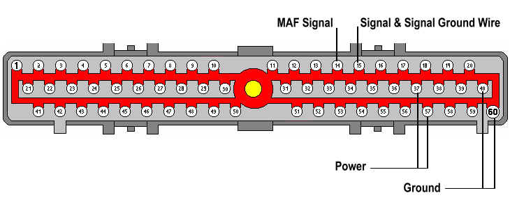
Installing computer and wiring everything up to it. Time, about 4 hours. Before starting, remove battery connections. Be careful of static electricity -- it can zap electrical components. 4.1 Remove passenger sidekick panel and expose computer. Unbolt computer support and remove harness (a bolt holds it on). Remove the old computer. 4.2 Depending on your year model, you will have from 4 to 9 wires to connect into the computers 60-pin connector. Terminals are provided with conversion harness for these to plug into. You will need 2 extra (order 4, as you will lose or break one) to connect self-test connector wires to pins 28 and 9. See 1990 computer wiring diagram to find out what goes where. This was easier than I thought it would be but did consume some time to study things carefully before proceeding. The 60-pin computer harness has wires inserted into it with special end connectors. The wires/end connectors can be pulled in/out and moved to other locations if needed, or new ones added simply. A small plastic cap fits over the outside of the 60-pin computer connector to secure wires after moving them around. A red plastic insert secures the wires inside. You need to loosen this to enable the connectors to be inserted easily. If they do not insert easy, you need to look at this again. You WILL need 2 of the special connectors if you are wiring up the speed sensor. The wiring kit comes with 3. I highly advise getting the somewhat overpriced kit and not trying to do this without all the right pieces. The MAF meter has 4 connections. 4.3 VPWR (red wire in kit) is spliced into the wire of either pin 37 or 57. To splice it, make a cut in the insulation of the wire in the area behind the connector. Strip away some of the plastic for about 1/4" (DO NOT CUT WIRE). Next, strip about 1/2" of insulation from the end of the wire to be attached. Wrap it around the other wire at the 1/4" exposed area and solder the connection. Wrap it with plastic insulation tape or coat with latex wire insulation material. 4.4 PWR GND (Black wire) is spliced into the wire of pin 40 or 60. 4.5 MAF RTN (Signal Ground) (Brown): the end of the wire has a terminal on it, which must be inserted into location 15 of the 60-pin connector. 4.6 MAF (signal), (Blue wire): the end of the wire has a terminal, which must be inserted, into location 14. 4.7 Pin 8, Fuel pump monitor: This connection is also required for the '86. If you already have a connection to pin 8 located in the 60-pin connector, you can skip this step. Maybe some others. But it's a real easy connection. You cut a small break in the insulation of the O/LB (orange/light blue) wire running from the fuel-pump inertia switch (located on the floorboard under the heater). FYI, this wire runs to the fuel pump relay located under the hood near the air-cleaner and you could connect it there as well, but its closer at the inertia switch. Strip the end of the wire, wrap around insulation cut and solder it. Tape over the solder area. Route wire over to pin 8 at the computer connector. 4.8 Solder all connections. Coat all joints with liquid insulation, and then tape over that. 4.9 I noticed that my '86 also had an extra power wire to location 5. I pulled it. All the other extra items (EGR & MAP related) were left intact. 4.10 Wiring notes: The wiring harness and instructions are originally for a 5.0L MAF ENGINE CONVERSION. So, in the Conversion Harness instructions -- they tell you where to insert the wires into the connector for the 5.0L MAF ENGINE conversion, which I have adopted here for the 2.9L wiring requirements -- (power and ground are the same for the 2.9L MAF conversion) --- splice them into either 37 or 57 for power, and 40 or 60 for ground. For the 2.9L, the Signal and signal ground wires need to be connected to the connector at location 15 (listed as location 9 for the 5.0L engine conversion, which we are not doing here), and location 14 for 2.9L MAF signal (pin 50 in the instructions for the 5.0L MAF conversion). You are given the pins that go into the connector, and the wires are soldered to the input side of the pin -- the other pin end then forms part of the connector like any other pin in it. 4.11 Pins 9 & 28 are listed in the 1990 wiring diagram for MAF vehicles. These are necessary to connect to enable getting computer codes during running tests. You can still get stored codes without the connections. 4.12 The 1990 wiring diagram shows the speed sensor connection at 6 is also grounded. You can form this ground by making a looping connection to 20. I ran for quite a while without it, but added it later. Not sure if its really needed or not. 4.13 The 1990 wiring diagram shows use of a 4 wire O2 sensor. My 1986 had a 3 wire sensor. I think you need to form a wire jumper from 46 to 49 to enable a good HEGO signal return (if you have a 3 wire O2 sensor). SECTION 5: 19lb Injector Installation. (not required). This is the most complicated step. Time, about 4-8 hours, depending on the cleaning required for intake manifold and injector passages. The steps here are abbreviated. Follow service manual to get detail for changing injectors. 5.1 Prior to starting, clean up the upper intake portion of engine as well as possible. Hose it down lightly and let dry. This will prevent possibility of dirt entering engine. 5.2 Remove various connections to the intake manifold -- throttle cable cover, throttle cable, connectors to sensors, vacuum lines, etc. 5.3 Unbolt the intake manifold and lift off. Immediately, cover the lower intake openings with a clean towels. Stuff them in so that nothing can drop in. 5.4 Remove the FOUR bolts which hold the fuel manifold in place. 5.5 Wiggle the fuel manifold around while lifting. Soon the whole assembly will come off with the injectors attached. If the assembly does not come out, check again to see if you got all FOUR of the bolts removed which holds it in place. 5.6 CAREFULLY remove the electrical connectors from the injectors. The side clips which hold the connector in place are fragile and break easily. Use a pocket knife and just pry away enough to remove connector. Note that each connector will have a number on it corresponding to the injector number. The injector numbers are also numbered on the top of the fuel manifold. 5.7 Pull the clips off the injectors that hold them to the fuel manifold. Pull injector out. CAUTION: Fuel will come out. Have a rag ready. 5.8 Clean up the holes in the lower intake where the injectors were. I used q-tips with engine cleaner or solvent to clean the openings well. You will need about 20-30 q-tips. 5.9 You may wish to install new o-rings on the new injectors, depending on the condition of them. Note: Ford sells a special O-ring for very cold climates that seal better. 5.10 Oil o-rings with motor oil and install injectors to fuel manifold. Install clips and then electrical connectors. Oil the outer o-rings and install the assembly into the lower intake. 5.11 Install the 4 bolts. The 2 on the side will drive you crazy to get started. I finally replaced these with Allen bolts and bought a special drive tool for them. 5.12. If you have not ported your upper intake, this is a good time. See Kunz tips for upper intake porting. 5.13 Use a new gasket and re-install upper intake. I found that the gaskets are not well matched to the casting, and cut the gaskets to match the casting so there is no restriction. 5.14 Re-connect all connections to the upper intake. SECTION 6: Notes on old engine sensors 6.1 MAP Sensor: Remove vacuum line leading from upper intake manifold to MAP sensor (vacuum line is no longer used). PLUG the hole on the intake manifold. Leave MAP sensor port OPEN to the atmosphere. Leave electrical connector connected to MAP sensor (don't ask me why). 6.2 EGR: If you have EGR (Exhaust Gas Recirculation), found on earlier 2.9L's: Good news: You can remove all the EGR related items and plumbing. Plug the vacuum holes and the exhaust manifold (I just put a bolt/nut into the hole in the existing fitting, and re-installed it). Items you can remove: EGR pressure transducer, EGR control solenoid, EGR recirculation valve, EGR sensors vacuum lines, EGR line from the exhaust manifold to the EGR valve. You can pull the vacuum fitting tree on the exhaust manifold and replace it with a 3/8" plug if you like. I really suggest you leave all the EGR plumbing in place till you are sure you really like the MAF conversion. At some future date, we may figure out how to still use the EGR, which helps reduce pinging in some cases. 6.3 Knock Sensor, if you have one: This is not used in the 1990 MAF system. You can leave it in place or remove it. I would leave it in place. We may figure out how to use it in the future. 6.4 Air Conditioning: If you find that your A/C does not come on -- there are some variations in wiring from year to year. My 1986 had this problem. I found that the WOT (Wide Open Throttle) Relay needed to be changed or disconnected. Some years have these normally powered on and some off. So, you can either unplug the power to the relay, or swap relays. Unplugging is easy. Mine had a 4 pin connector with 3 wires to it -- 2 red and one green/black. The connector is located near the WOT relay, which for mine is one the passenger side fender in the engine compartment. 6.5 O2 Sensors: The 1990 MAF computer wiring diagram shows using a 4 wire O2 sensor. Some 1986 trucks (maybe others too) use a 3 wire O2 sensor. For these trucks, it may be required to form a jumper connection from pin 46 to pin 49 to effect proper EGO signal return. I ran mine for months without it, and did not have a problem. Later I formed the connection to try and solve a pinging problem that arose. The connection did not fix the pinging problem. So I guess you can leave it as is. 6.6 Speed Sensor: If you have a speed control system or later model 2.9L, you probably have a speed sensor. This is good, as you will not have to install one. 6.7 ISC Valve: The 1990 MAF computer wiring diagram lists a somewhat different part number for the idle speed control valve. I ran my old one, which looks identical, without a problem for quite a while. When it was time for a new one, I switched to the one that was called out on the MAF computer wiring diagram. 6.8 Fuel Pump Monitor and Vehicle Speed Sensor: Snippet from SN95 site -- "You won't have any problems. Pin 3 is the VSS+ pin, pin 6 is the VSS- pin and 19 is the Fuel Pump Monitor pin. After spending 8 years going through the Mustang EEC, I haven't seen much that deals with the VSS sensor. Cruise yeah, idle no. The missing Fuel Pump Monitor doesn't do much either. The EEC uses it to see if the pump is doing what it's supposed to be doing (off or on). I don't have any of this stuff in my car and after 30K miles not a lick of trouble. You will get error codes though. If Ford thought there would be a problem with not having a VSS sensor, they would have put it in their kit or technically they would be liable for any problems. All that's really needed is to make sure the thermactor wires are swapped around so it operates correctly. SECTION 7: AIR ADJUSTER INSTALLATION (SUGGESTED OPTIONAL UPGRADE). Time required: less than 1 hour. The "Air Adjuster" is a digital electronic display and MAF meter calibration system which attaches in-line to the MAF meter. It enables one to fine-tune the MAF meter to the injectors and other engine modifications. These can help in fine tuning or in determining optimal MAF re-calibration. 7.1 What you need: Part Number: AA-9999-F, Air Adjuster, from IST, cost $150. 7.2 Installation: Simple. With engine off, unplug existing plug from MAF sensor. Plug the male connector into the harness connector you just removed and plug the female connector into the MAF sensor. 7.3 Place Direct/Adjust switch to direct and start engine. Record baseline voltage after engine is warmed up. 7.4 Adjustment: Flick switch to adjust and adjust screw to baseline voltage. Then, follow instructions (simple). SECTION 8: Getting Going: 8.1 Congratulations: You are ready to go! 8.2 After firing it up and getting things settled. Rotate the MAF meter about 45 degrees in either direction. Find the location where you get fastest idle and best air-fuel readings. You should have about 0.8v at normal idle. The voltage is that read out from the Air Adjuster before adjusting anything. 8.3 Anytime you change anything in the air intake system you may need to rotate MAF meter, fine tune with Air Adjuster, or re-calibrate system. A. MISC. DIMENSIONAL & RELATED MAF NOTES, FYI: * 5.0L MAF: 82.2mm intake side of MAF, 55mm center area, 70mm output side, into a 70mm ID hose. The input hose is huge: 90mm ID. This MAF meter is calibrated to run with 19lb. injectors. * STOCK 1990 2.9L MAF INFO: The stock 45mm unit is the same part number unit as used on a 2.3L engine. Both are 71.2mm intake side, 44.8mm center area, 56.1 mm output side, feeding into a 68mm ID hose. The input bolts to the airbox. The stock MAF meter and computer are calibrated to run with 14lb. injectors. * The largest remaining restriction on the intake system is the inside of the 5.0L MAF meter at 55mm. Next is (in my case) the 1986 throttle body at about 58mm, finally the stock intake hose connecting from the airbox to the MAF meter -- 70mm inside diameter. I'd like the last piece to be larger, but I am not sure it matters that much yet. Using the 5.0L parts for this conversion enables an easy upgrade to a larger (5.0L type) MAF meter in the future, if needed. By the way, I read that a 54mm MAF sensor will flow 900 CFM. * Pat Kunz recommends that the MAF sensor be calibrated to the engine and injectors. This can be done by sending it to Best Products, Inc. (Pro-Flow). You can find out about them at http://www.pro-flow.com/. FYI, Pro-Flow has a product called the Optimizer that enables you to do your own calibrations if you like. Or you can install the Air Adjuster noted herein. * Ken Funk noted: "My stock 1990 MAF truck took a special O2 sensor. The NAPA part # is OS205. Its an expensive little bugger, cost about $90. From Kenny Funk [mailto:kfunk@utahlinx.com] I'll give you all the part #'s off of the sensor part of the MAF: FOVF-12B579-A2B AFH45-25 And the 4 digit code is: 9M14 B. WIRING DIAGRAMS: Best source: The Ford "Electrical & Vacuum Trouble Shooting Manual" or page copies, for both your model and the 1990 model. Your Ford dealer can make copies of theirs for you. You want to ask for the "Electronic Engine Control" pages if you are asking for copies. C. EXAMPLE OF A PIN OUT COMPARISON BY NUMBER BETWEEN AN '86/'87 SPEED DENSITY SYSTEM '90 MAF SYSTEM I advise you to check your exact wiring diagram for any differences. The 1986 model is the hardest to wire (mine). The 1988-1992 models have some different wiring changes. Check your exact schematic.
D. SUPPLIERS & USEFUL REFERENCES: A. All Mustang Performance and Recycling. The place specializes in high performance Mustangs and buys wrecked ones to salvage parts off of. They have several in inventory which have set-ups like the one I got. Good folks. Contact Tom Thompson 602-437-2727 (Phoenix). If interested, tell them I sent you. B. Ford Motorsports: 1-800-782-4356. Get the 1999 Ford Motorsport SVO Catalog. On pages 18 and 58, you can find factory components for doing a 5.0L conversion. They also show an instruction book that can be purchased and may be useful. C. Pro-Flow (Best Products, Inc.): OUT OF BUSINESS - Best Products went out of business in 2005. At this time, we do not know where to get a MAF recalibrated. If you perform the swap successfully, please contact us and let us know what you did about the recalibration. admin@therangerstation.com D. EEC Handbook: http://www.dalidesign.com/hbook/intro.html (Link no longer good) E. Joe Aubertin's EEC Page: http://www.iaw.com/~aubertin/88mgt/eec-iv/eec-iv.htm F. Fuel injector info: http://efi332.eng.ohio-state.edu/diy_efi/oem/ford/ford.txt G. IST, Interactive Systems & Technologies. Canton, GA. 800-820-1082, http://www.mass-air.com (but web site was not working when last checked). H. Force Fuel Injection, 8765 SW 129th Street, Miami, FL 33176-5916 Ph: 305-235-6160, Fx 305-235-4241, http://www.force-efi.com I. Jasons EEC page: http://www.paperrat.com/eec/ (Link no longer good) Andrews EEC-IV page: http://www.icenet.com.au/~amarch/eec.htm J. Ford Fuel Injection.com http://www.fordfuelinjection.com/ E. PINGING and MAF: I started experiencing pinging (detonation) with some gas changes after a few months of running. This was fixed by doing a re-calibration of the MAF meter as noted previously. MAF engines ARE more sensitive to pinging. This is because, in my opinion, MAF uses more sensors to calculate the "correct" air-fuel mixture, and MAF attempts to calculate much closer air/fuel ratios than the speed density systems which run a bit richer. Also this is due to all the modifications to the engine we have made. SOME of the stock 2.9L speed density systems incorporated knock sensors which enabled the engines to tune in the optimum ratios a bit closer (limited range), but the 1990 MAF computer for the 2.9L DOES NOT have a knock sensor provision (big oops by Ford). Prior to fixing it, the most common pinging I encountered was under part throttle acceleration conditions (3-4000 rpm, engine warm, cruising along and acceleration less that WOT), on hotter days (engine running warmer than normal). Many things can cause the pinging. Too advanced timing, carbon build-up, poor fuel, insufficient fuel pressure or flow, and other factors, AND VERY COMMON by mis-matched components (MAF meter, injectors and computers advance/injector timing curves). The larger MAF flows more air than the engine thinks for a similar voltage, and therefore the engine runs lean. Under this condition (engine warm, part-throttle acceleration) the engine calculates fuel injector pulse time from the computer look-up tables and inputs from throttle position sensor (amount and rate of throttle opening), MAF (load of air), PIP (rpm), ACT (air temp/density), and ECT (engine coolant temperature), and O2 sensor. Malfunction of any of these can result in pinging. Reading the codes from the computer, you can learn many things. The MAF computer has additional codes that can help you pinpoint many problems. Your biggest friend will be the air-fuel ration gauge. Engine timing and higher-octane gas are the first things you can do to reduce pinging. But this can reduce HP. Reducing engine operating temp helps too. These are temporary solutions. You need to get to the root cause of any pinging problems and fix them. ---------------------------------------------------------------------------------------------- Please email me any corrections or comments so that I can add them to future revisions. Happy Trails, Bob Marrs NOTE - If anyone has completed this conversion and would like to update it, please contact us at admin@therangerstation.com
|
|
|