
Overview:
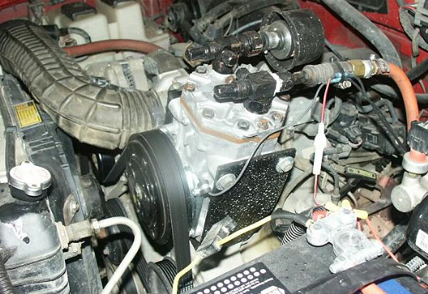
Many off-road enthusiasts get to a point where they find a need for onboard air. Whether it’s for airing up tires, lockers, or using air tools. There are a variety of options including electric air compressors, belt driven air compressors, and CO2 tanks. This page discusses the use of the York air conditioning compressor as an onboard air compressor.
Why Should You Use A York A/C (Air Conditioning) Compressor:
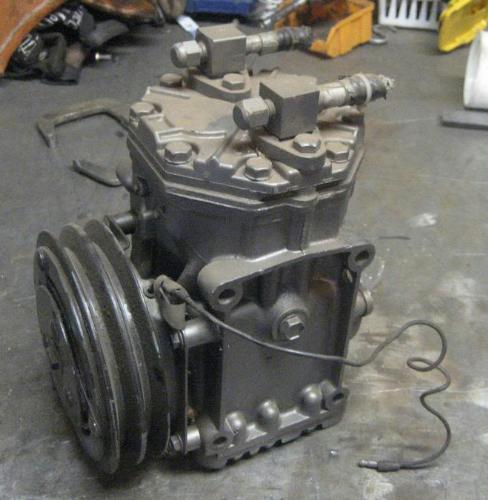
(York A/C Compressor)
Most A/C compressors used on vehicles are lubricated by the freon running through the system. Since it’s a sealed system, it stays lubricated. If you use one of those compressors to pump air, it won’t get any lubrication and will seize up. You could add an external oiler, but you’d have to deal with separating the oil out of the air and routing it back to the compressor.
Unlike these compressors, the York has an internal reservoir for oil. So if you remove the freon and use it to pump air, it will still lubricate itself.
There are a few different York compressors to choose from, and some pump more air than others.
Which York To Choose:
There are (3) variations of the York compressor:
- Long stroke 210 Series =10.3 ci (169 cc)
- Medium Stroke 209 Series – 8.69 ci (142 cc)
- Short stroke 206 Series = 6.10 ci (100 cc)
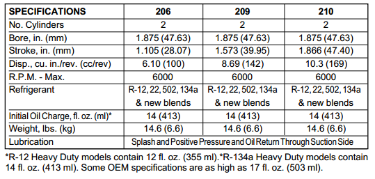
The most desirable York compressor is the 210. It’s longer stroke gives it more volume, resulting in more CFM (Cubic Feet per Minute). The 210 is rated at 4 CFM @ 90 PSI, and is capable of 8+ CFM. The larger CFM allows it to run air tools.
You can identify a York compressor by the ID plate.
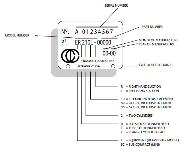
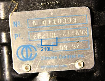
(This tag identifies this compressor as a York 210 with a left hand suction)
If your York came out of an AMC or Ford, than you likely have a non-standard ID plate.
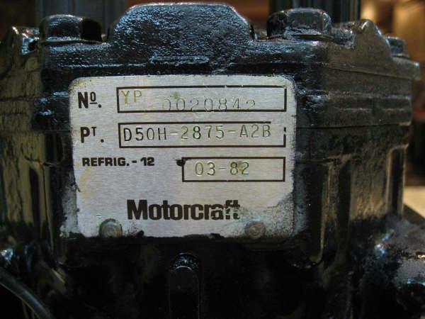
(York compressor with a Motorcraft tag)
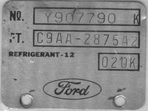
(Ford tag on York compressor)
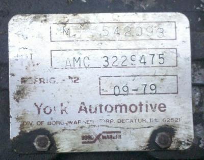
(York tag from a York compressor on a 1979 Jeep CJ7)
In that case, you may have to remove the pulley and look at the end of the shaft. You’ll need a 1/2″ socket, a 5/8″ course thread bolt, and a 15/16″ socket to pull the pulley.
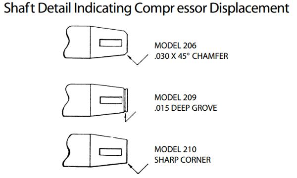
Using the diagram above, you can see that each compressor has a different detail to its shaft that helps identify it.
Here is a list of vehicles that came with the York 210 compressor:
Note: There are two types of York upper fittings: ‘Flange’ mount and ‘Tube O-Ring’ (a tube inside a rubber O-ring).
| Vehicles That Came With A York 210 Compressor | |||
| Audi | |||
| Model | Year | Head Type | Suction |
| 100LS | 1976-1977 | Tube o-Ring | Right |
| Ford | |||
| Model | Year | Head Type | Suction |
| Bronco | 1978-1981 | Tube O-Ring | Left |
| Bronco | 1978-1983 | Flange | Right |
| Country Squire | 1975-1984 | Flange | Right |
| Crown Victoria, LTD Full Size | 1975-1984 | Flange | Right |
| E Series Van | 1976-1982 | Tube O-Ring | Left |
| E Series Van | 1976-1985 | Flange | Right |
| F Series Pickup F-150-F350 | 1976-1981 | Tube O-Ring | Left |
| F Series Pickup F-150-F350 | 1980-1985 | Flange | Right |
| Fairmont | 1979-1982 | Tube O-Ring | Left |
| Fairmont | 1979-1983 | Flange | Right |
| Granada | 1980-1982 | Tube O-Ring | Left |
| Granada | 1976-1982 | Flange | Right |
| LTD II | 1983-1984 | Flange | Right |
| Maverick | 1976-1977 | Tube O-Ring | Left |
| Maverick | 1976-1977 | Flange | Right |
| Mustang | 1976-1981 | Tube O-Ring | Left |
| Mustang | 1979-1984 | Flange | Right |
| Pinto | 1976-1980 | Tube O-Ring | Left |
| Pinto | 1976-1980 | Flange | Right |
| Ranger | 1983-1984 | Flange | Right |
| Thunderbird | 1977-1982 | Tube O-Ring | Left |
| Thunderbird | 1980-1988 | Flange | Right |
| Torino | 1976 | Tube O-Ring | Left |
| Torino | 1976 | Flange | Right |
| Jeep | |||
| Model | Year | Head Type | Suction |
| Cherokee | 1976-1983 | Tube O-Ring | Right |
| Cherokee | 1976-1983 | Flange | Right |
| Comanche | 1986-1988 | Tube O-Ring | Right |
| Grand Wagoneer | 1984-1991 | Tube O-Ring | Right |
| Wagoneer | 1976-1983 | Tube O-Ring | Right |
| Mercury | |||
| Model | Year | Head Type | Suction |
| Bobcat | 1976-1980 | Tube O-Ring | Left |
| Bobcat | 1976-1980 | Flange | Right |
| Capri | 1979-1982 | Tube O-Ring | Left |
| Capri | 1979-1984 | Flange | Right |
| Colony Park | 1980-1984 | Flange | Right |
| Comet | 1976-1977 | Tube O-Ring | Left |
| Comet | 1976-1977 | Flange | Right |
| Cougar | 1976-1982 | Tube O-Ring | Left |
| Cougar | 1976-1982 | Flange | Right |
| Grand Marquis | 1983-1984 | Flange | Right |
| Marquis – Full Size | 1980-1982 | Flange | Right |
| Marquis – Mid Size | 1983-1984 | Flange | Right |
| Monarch | 1980 | Tube O-Ring | Left |
| Monarch | 1976-1980 | Flange | Right |
| Montego | 1976 | Tube O-Ring | Left |
| Montego | 1976 | Flange | Right |
| Zephyr | 1978-1982 | Tube O-Ring | Left |
| Zephyr | 1978-1983 | Flange | Right |
| Porsche | |||
| Model | Year | Head Type | Suction |
| 911 | 1978-1983 | Flat Top | Right |
| 914 | 1973-1976 | Flat Top | Right |
| 930 | 1977-1979 | Flat Top | Right |
| Volvo | |||
| Model | Year | Head Type | Suction |
| 240 Series | 1975-1984 | Flange | Right |
Volvo and AMC hose connections run horizontally across the top of the York, while Ford hose connections stick straight out.
Identifying The Suction Side And Discharge Side:
To determine which port is the suction, and which is the discharge, look at the head around where the hoses attach. The area around the ports will have a ‘S’ or ‘D’ for ‘suction’ or ‘discharge’. The may also be labeled as ‘SUCT’ or ‘DISCH’
Testing The Compressor:
The York compressor will have a single wire coming off of it. Ground the compressor and apply 12 volts to the wire. You should hear a click from the clutch engaging. With it engaged, you should hear air coming out of the port when you turn the pulley. When you disconnect the power, the pulley should turn freely (with less resistance) and should not be pumping air.
Checking The Oil:
The standard York has an oil fill/check hole in the center of each side of the compressor body. They’re plugged with a bolt with a 1/2″ hex head, and sealed with a rubber O-ring.
Make the initial oil level check after the compressor is mounted on the mounting bracket.
Remove one oil fill plug with its O-ring. Either plug on a vertical mount installation, and the upper plug on horizontal mount installations. You can make a dipstick to check your oil level.
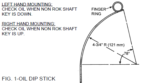
The oil dip stick, Fig. 1, can be made locally, and is suitable for use on all compressors in any mounting position. It can be formed from 1/8″ diameter x 8-5/16″ (3 mm diameter x 210 mm) long stock, preferably non ferrous material which is not subject to corrosion. Notched ends are helpful in visibly detecting the oil depths.
Compressor Oil Type:
When adding or changing oil, use only proper oil. Keep the oil storage container tightly capped at all times. Here is the recommended oil when the compressor is being used as an actual air conditioning compressor:
| Refrigerant | Acceptable Lubricants |
| R-12, R-22, R-502 | Mineral Oil, Zerol 150, Zerice S-68, P.O.E. |
| R-134a | Polyol Ester (P.O.E.) P.A.G. |
You don’t have to use those accepted lubricants when you’re using it as a regular air compressor. People converting these compressors for onboard air usually drain all the oil out and refill them with 10W-30 motor oil. Some have even used ATF.
The Table below shows the crankcase oil level in fluid ounces (and ml) at various dip stick measurements for both horizontal and vertical mounts. The oil level after the system is stabilized should be maintained with 6 fluid ounces (177 ml) minimum and 8 to 12 fluid ounces (237 to 355 ml) for best results.
Oil Level vs. Dip Stick Depth:
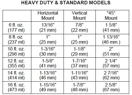
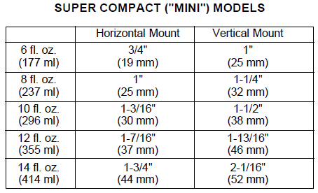

The compressor oil level should never be permitted to go below the minimum oil level of 6 fluid ounces (177 ml). If oil must be added, the oil should be added until the level is 12 fluid ounces (355 ml). An excessive amount of oil is detrimental to the proper functioning of the entire system.
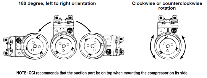
Mounting The York:
The York compressor can be mounted flat, angled or upright. The suction port should always be on top when mounted at an angle. Also, the compressor will work whether it’s spun clockwise, or counter clockwise.
Compressor Fittings:
Volvo and AMC hose connections run horizontally across the top of the York, while Ford hose connections stick straight out of the top.
The problem people run in to is connecting to the hose fittings on the compressor.
Converting The Fitting:
The York compressors use a 5/8″ flare on the suction side and a 1/2″ flare on the pressure side.
Pressure Side:
On the pressure side, people have converted the 1/2″ Flare to 3/8″ male NPT by using:
1/2″ Flare to 1/2″ Flare Swivel Union
1/2″ Flare to 3/8″ NPT adapter
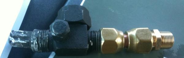
Another example using an elbow:
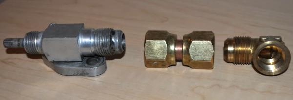
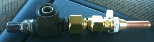
Suction Side:
They have converted the suction side to 1/2″ OD Copper so they could slide a filter on. This was done using:
5/8″ to 1/2″ flange swivel union
1/2″ to 1/2″ flare
1/2″ flare nut to piece of 1/2″ copper
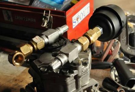
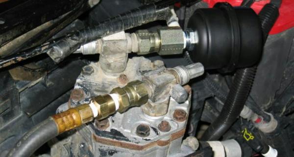
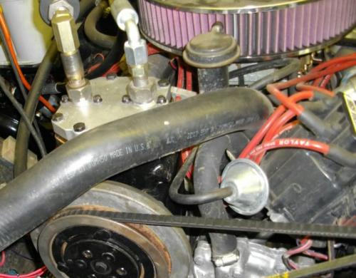
When you remove the factory A/C lines, the threaded fittings that remain are standard 45-degree flared gas line (JIC) fittings. The intake fitting is 1/2″ (-8) and the discharge fitting is 5/8″ (-10). In the photo above, the owner swapped the factory fittings side to side so that the larger fitting was on the intake. He used a 1/2″ flare to 3/8″ NPT fitting and a 3/8″ to 1/4″ NPT reducer to connect the factory discharge fitting to an air hose. The air filter is attached to the factory JIC fitting using a 5/8″ flare to 1/2″ NPT adapter purchased from a hydraulic supply shop (Grainger sells them).
The filter is a Solberg FS-06-050.
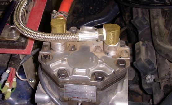
Others have removed the factory connectors and head, drilled and tapped the inside of the factory fittings to accept a 3/8″ NPT fitting, and used 3/8″ NPT 90 degree elbows.
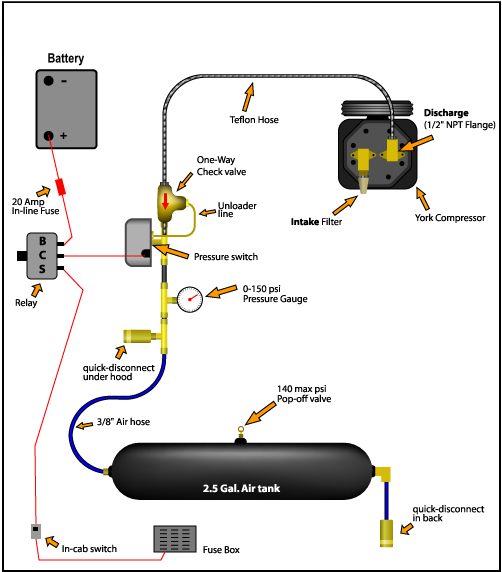
Making It All Work:
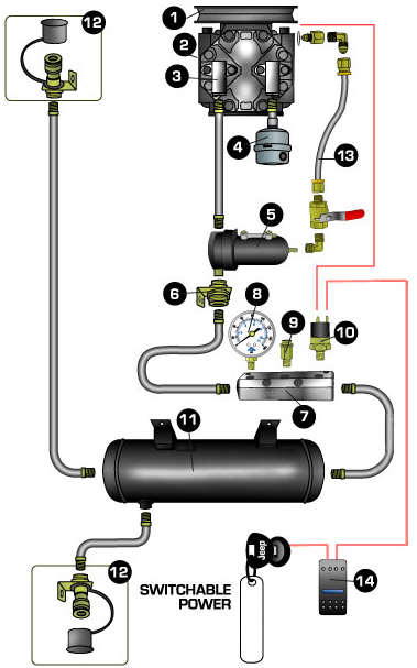
| Item # | Item Description | Item Use |
| 1 | Compressor Clutch | Engages & disengages the compressor |
| 2 | Compressor | Compresses air to fill the tank |
| 3 | Compressor Fittings | Connects the lines to the compressor |
| 4 | Intake Filter | Makes sure your compressor only runs on clean air |
| 5 | Coalescing Filter | Removes oil from the air coming out of the compressor |
| 6 | Check Valve | One way valve. Not needed if you’re not running an air tank |
| 7 | Air Manifold | A union to place the safety valve, gauge, and pressure switch |
| 8 | Pressure Gauge | Allows you to see how much pressure is being generated |
| 9 | Safety Valve | A pressure relief valve that will open to release pressure if the pressure switch fails |
| 10 | Pressure Switch | Turns the compressor on/off depending on the air pressure in the system |
| 11 | Air Tank | Stores compressed air |
| 12 | Air Couplers | Allows you to connect air tools and tire chucks |
| 13 | Oil Return Kit | Routes oil from the filter back to the compressor |
| 14 | ON/OFF Switch | Sends power to the pressure switch to turn the compressor ON/OFF |
This isn’t a very complicated setup.
12-Volt Switch:
You need the in-cab switch to override the system so you can shut it off if needed.
It’s best to use a relay to run the power for your pressure switch off the battery. When the switch in the cab is activated, the power turns on the relay, which sends the power to the pressure switch.
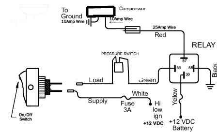
Pressure Switch:
The compressor pulley constantly turns with the engine. When you activate the switch in your cab, the power goes to a pressure switch. If the pressure is low, it send power to activate the clutch in the compressor. It fills the air in to your tank until the pressure switch shuts off. Companies such as VIAIR make pressure switches with different ON/OFF PSI settings. Some even include a relay.
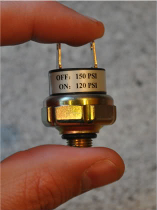
(Pressure switch)
Safety Relief Valve:
A safety relief valve is used (usually on the tank) to release pressure if the switch fails to shut off the compressor. This keeps the tank or hoses from blowing apart. Make sure your pressure switch is set to shut off 15-25 PSI less than your safety valve. This will keep it from accidentally blowing the valve and emptying your system.
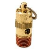
(Safety relief valve)
Air Regulator:
It’s not shown in the above diagram, but you should include an air regulator with a gauge somewhere after the pressure switch, and before the air chuck. This will allow you to control the air output if you want to run air tools.
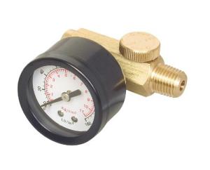
(Air regulator with a gauge)
Filter:
You’ll want a filter to remove water and oil from your air. You can even find them with a built in air regulator.
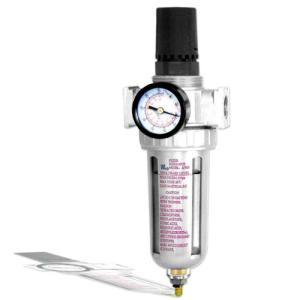
(Coalescing filter)
Air Tanks:
VIAIR makes air tanks ranging in size from 0.5 gallons to 5 gallons.
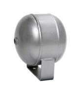
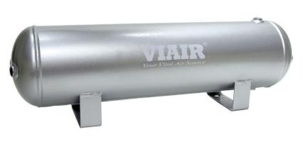
(You’ll need an air tank)
Add a quick disconnect at the tank with a hose long enough to reach every point of the truck.
More Diagrams:
There you go! We hope you find this page helpful. Please post photos and details of your project in our Discussion Forum.
Resources:
About The Author
Jim Oaks is the founder of TheRangerStation.com, the longest-running Ford Ranger resource online since 1999. With over 25 years of hands-on experience building and modifying Ford Rangers — including magazine-featured builds like Project Transformer — Jim has become one of the most trusted authorities in the Ford Ranger off-road and enthusiast space.
Since launching TheRangerStation.com, Jim has documented thousands of real-world Ranger builds, technical repairs, drivetrain swaps, suspension modifications, and off-road adventures contributed by owners worldwide. TheRangerStation.com has been referenced in print, video and online by enthusiasts, mechanics, and off-road builders looking for practical, and experience-based information.