So I was looking at my truck one day, and noticed my drop-pitman arm was kind of shiny and wet. Upon closer inspection, I noticed that my steering box was leaking! So rather than let it continue to leak and potentially (or at least, I thought it could) blow the box I opted to repair it.
I could’ve just replaced the seal that was leaking, but either way id have to rip the box totally apart. So I opted to rebuild it now, so I don’t have to do it again six months from now.
This was my first time disassembling a steering box, so I was taking my time. Didn’t want to screw anything up and have to do it all over again!
There are some special tools required to do this. But I don’t own any of them, so I had to get by without them! All you really need is a socket set, snap-ring pliers, and something to drive out/in the bearings and seals (I used large (over 1″) sockets). Oh, and a BFH will help out as well.
I’m going to try to cover everything I did, from start to finish, but I’m not going to cover removal and re-installation of the box in detail. Its very easy to do (even though its kind of heavy). 3 bolts through the frame, 2 pressure lines, the pitman arm nut, and the bolt that holds in the steering shaft to the box. If you cant figure out how to do that, then I recommend you do not rebuild your box yourself!
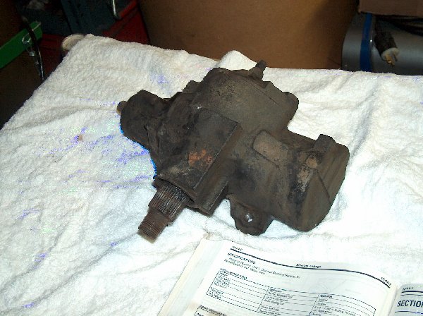
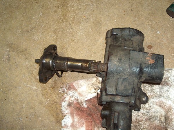
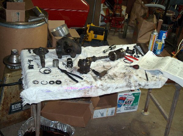
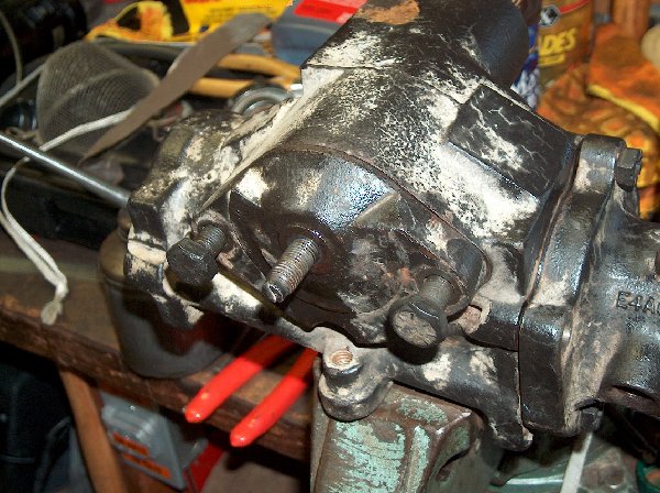
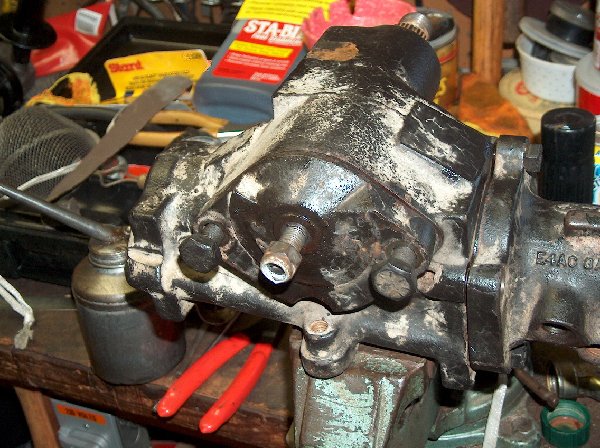
Here she is, laid out on the operating table!
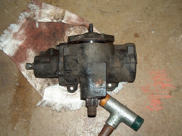
Now, before you begin dismantling the box, you need to drain it of all fluid. Turn it upside down, so the ports where the lines connect are facing down (into some sort of pan or tray) and rotate the input shaft from lock to lock. This will pump out all the fluid inside the box. There will be about a half-quart in the box, so it will take several turns before you get all the fluid out.
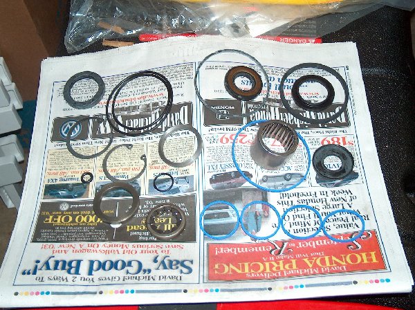
This is a pic of what comes in the rebuild kit. Kind of intimidating!
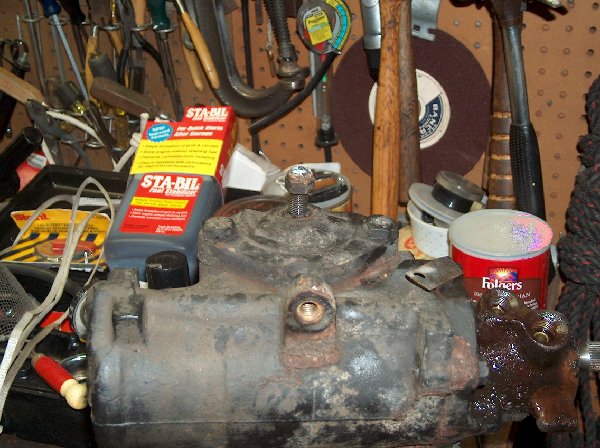
Ok, This pic shows the sector shaft adjustment nut loosened up, but don’t actually do this. Turning this screw will adjust the Return to Center on the box. This set screw adjusts the backlash between the sector & input shafts, so only adjust it if the box is too tight or too loose. Making it too tight will cause the box to wear at an accelerated rate, so only adjust it to remove excessive slop.
Step 2: At this point you need to center your box before you attempt to go further. Do this by turning the Worm Drive clockwise until it hits the stop, and then turn it back 2 turns. The flat spot should be facing down (when the box is properly oriented)
Step 3: Remove bolts holding cover-plate.
Step 4: Take a rubber mallet, or some form of hammer, and tap the bottom of the Sector Shaft until the whole assembly unseats itself. This will not work unless the box has been centered.
Step 5: Remove the Sector Shaft from the box.
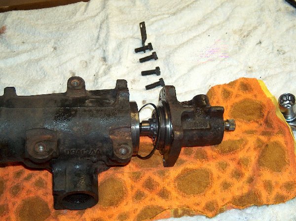
Step 6: Remove four bolts holding the valve housing (on top of input shaft). Pic is kind of fuzzy, but you get the idea.
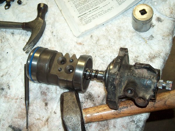
Step 7: Remove housing. Worm Drive and Piston will come out with it. Take note of O-ring- this will be replaced later.
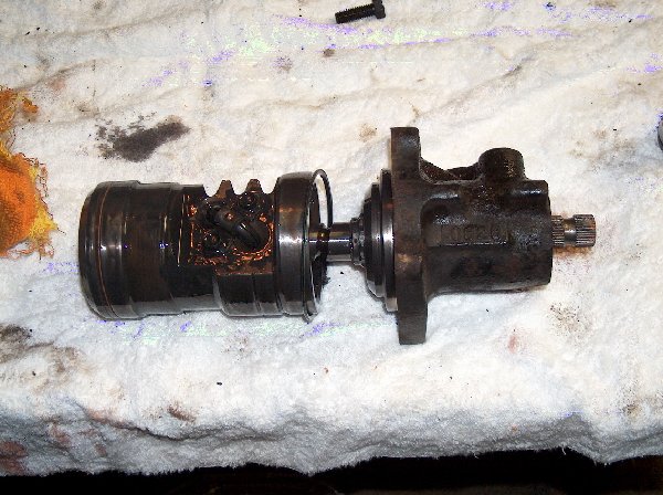
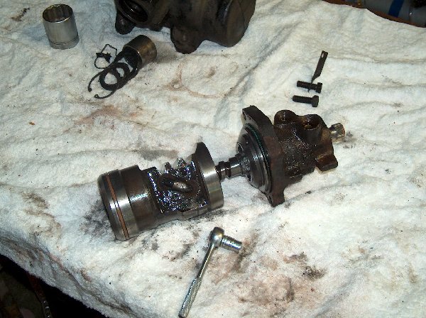
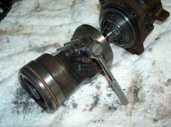
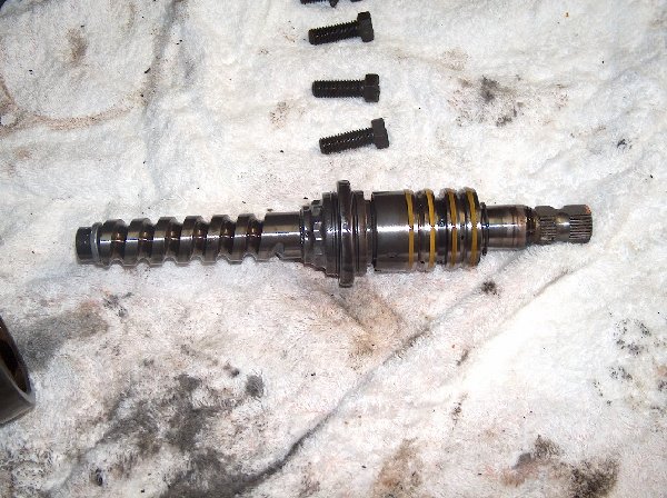
This is a pic of the removed Worm and Valve Assembly. This is what makes it all work!
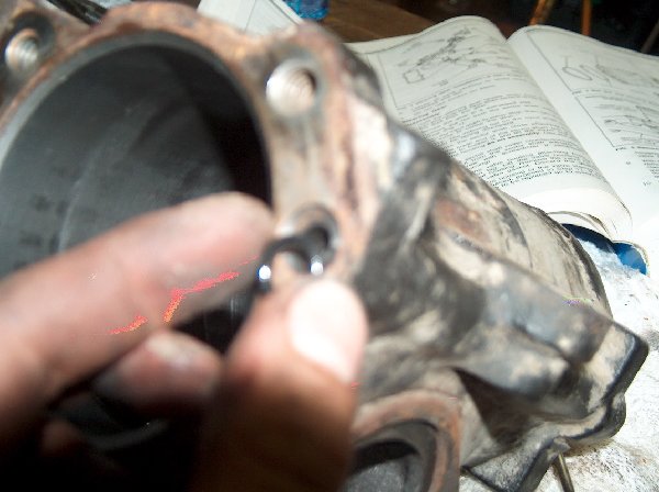
This is just a pic of the housing without the Worm and Valve assembly. Note the small O-ring in upper right hand side of the pic. This should be replaced when you put the box back together.
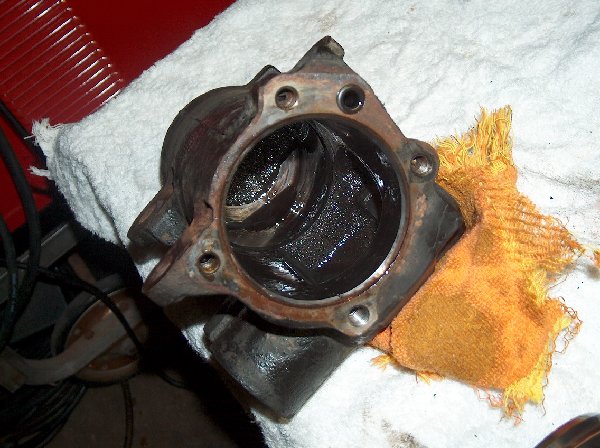
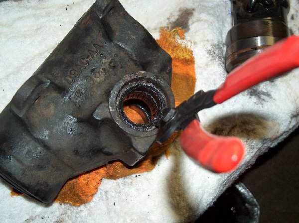
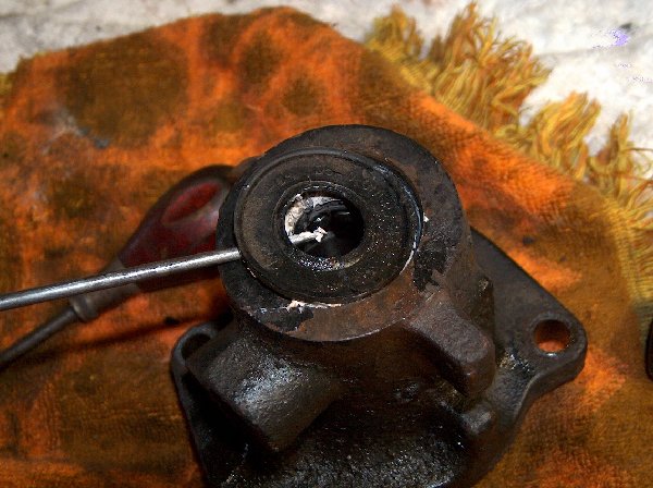
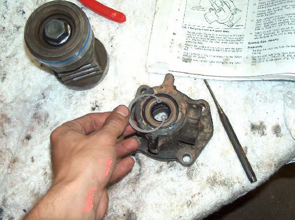
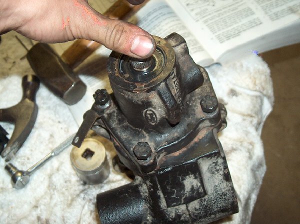
Step 8: Turn housing upside down, and remove snap-ring from sector shaft opening. This will allow you to remove the roller-bearing, pressure seal and dust seal.
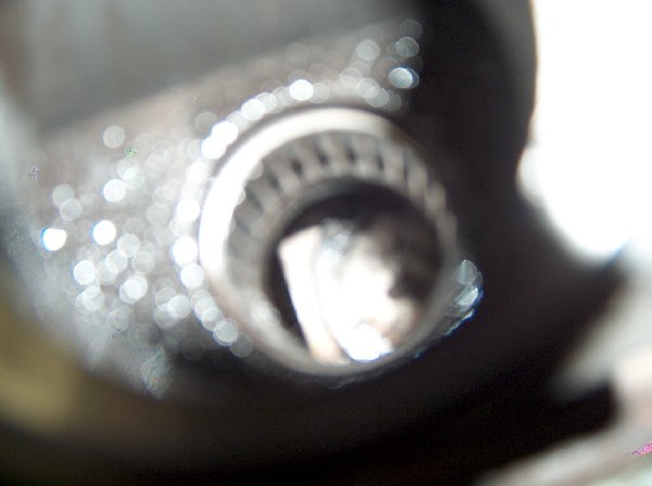
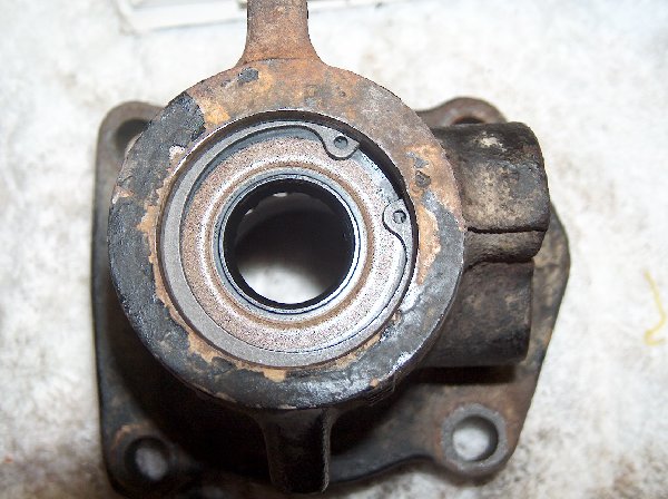
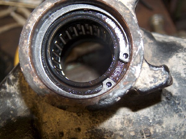
Step 9: Looking down into the housing. (right-side up). Fuzzy pic, but it shows the bearing.
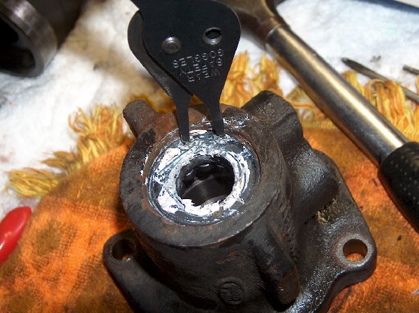
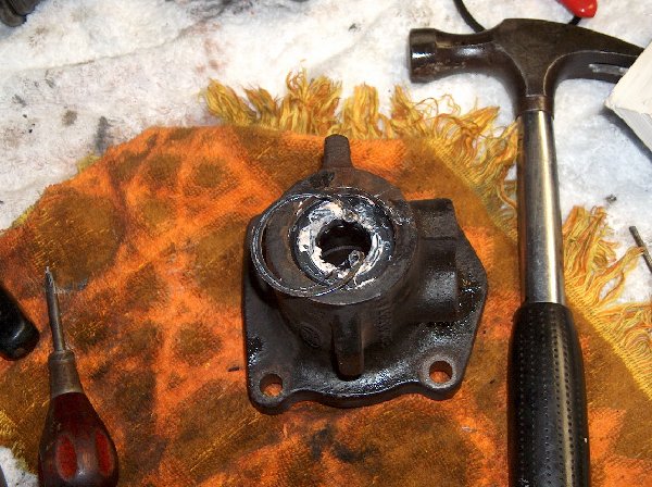
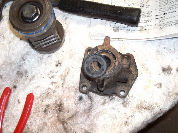
Step 10: Drive out bearing and seals. I used a large socket (facing backwards so the flat side was against the bearing) and an extension to hammer them out.
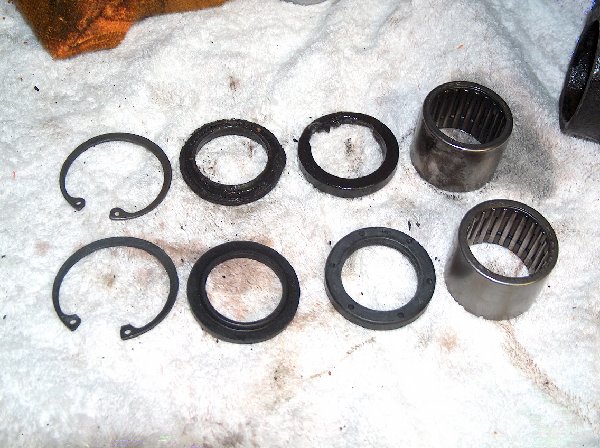
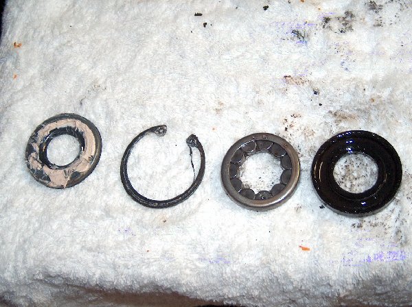
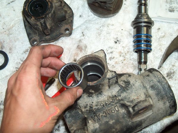
Just a pic showing the old bearing, seals and snap-ring above the new ones.
Now, back to the Worm Drive and Valve housing!
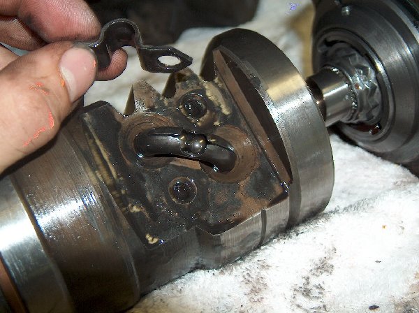
Step 11: Looking closely will reveal a u shaped strap bolted down over top of a U-shaped tube (also known as the Ball Guide). Remove the strap.
This shows the removal of the strap, and the exposed Ball Guide, which is actually two halves.
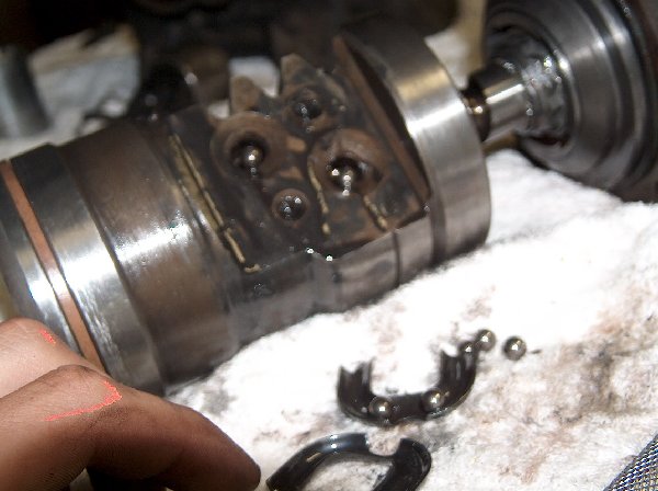
Step 12: Remove the Ball Guide. Be careful as there will be ball bearings inside that will fall out.
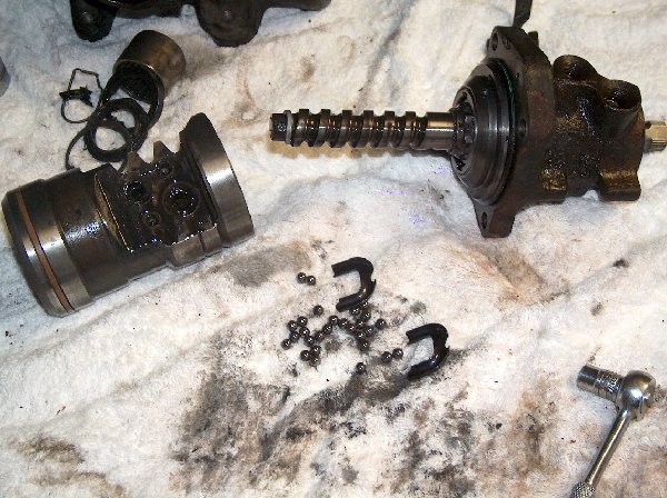
Step 13: Hold the Piston so that the Ball Guide holes are facing down, and rotate the valve housing from lock to lock. Several more ball bearings will fall out. The number varies from box to box, but it will always be between 27-29 balls. Count them, and put them somewhere safe, as the box will not work properly if you forget to put a couple back in.
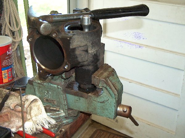
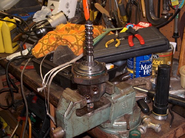
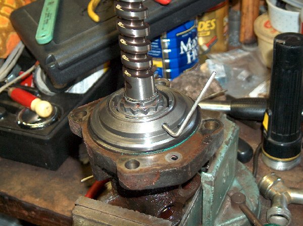
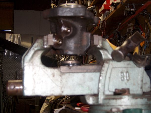
Next up is the removal of the Worm Drive from the Valve Housing. To do so you will need to secure the housing somehow. A vise will work fine.
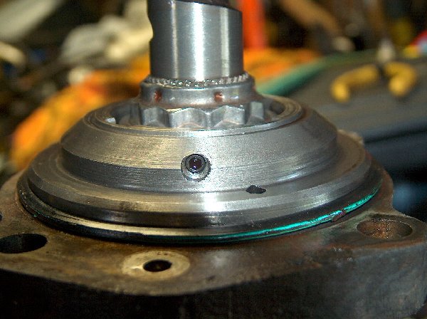
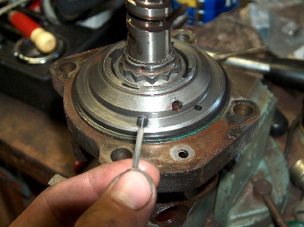
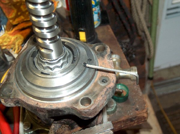
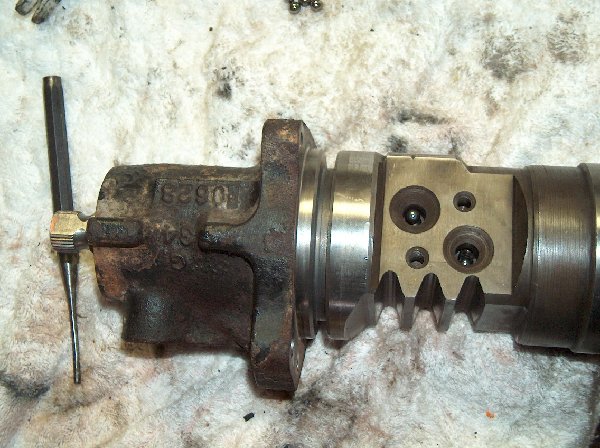
If you look closely you will notice a small set screw.
Step 14: Remove it!
See? I told you it was small!
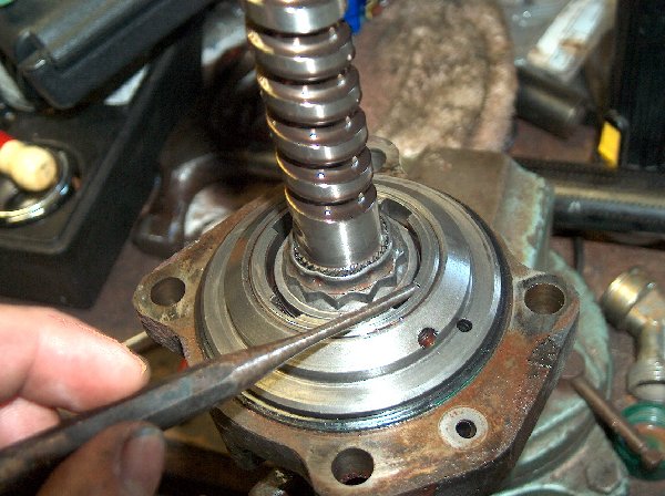
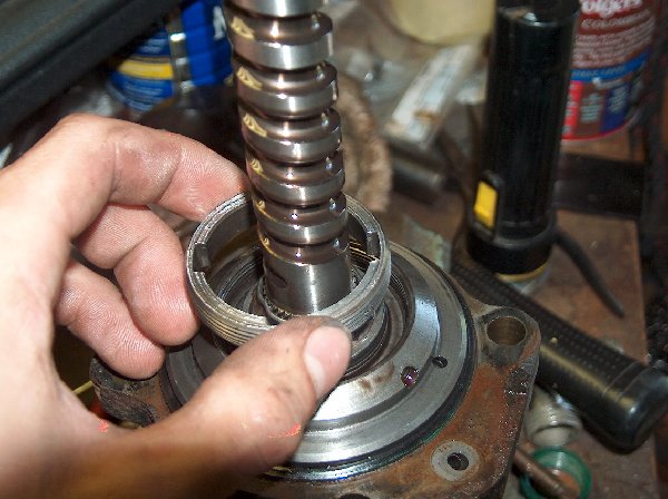
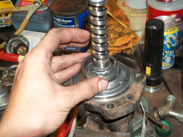
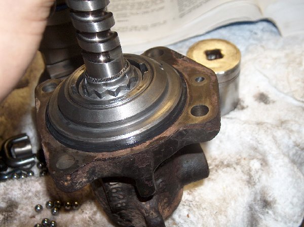
Step 15: Now that the set screw is out, you are free to remove the Worm Bearing Race Nut. There is a special tool that they claim is required to remove it, but I just used a drift and tapped on it until it came loose.
Pic of the nut removed.
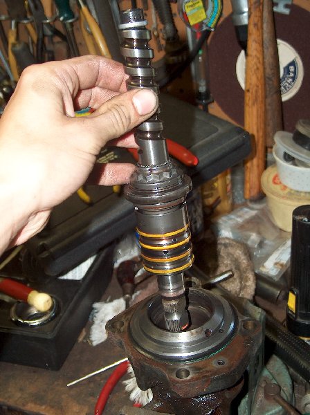
Step 16: Remove the Worm drive from the Valve Housing. It should come out fairly easily.
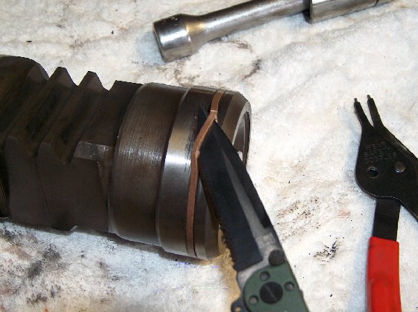
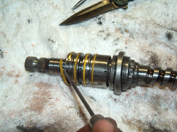
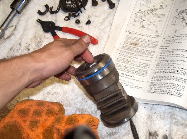
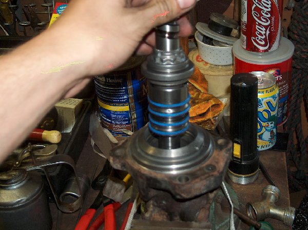
This is a pic of the Worm drive removed. Those 4 yellowish bands are Teflon seals that will need to be removed (just cut them off) and replaced before reassembly.
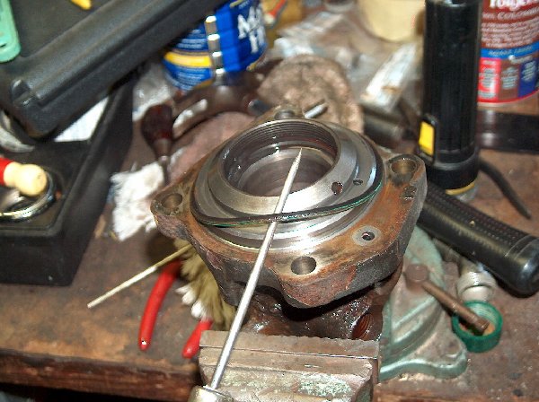
There is a flat seal on the housing that will need to be replaced as well.
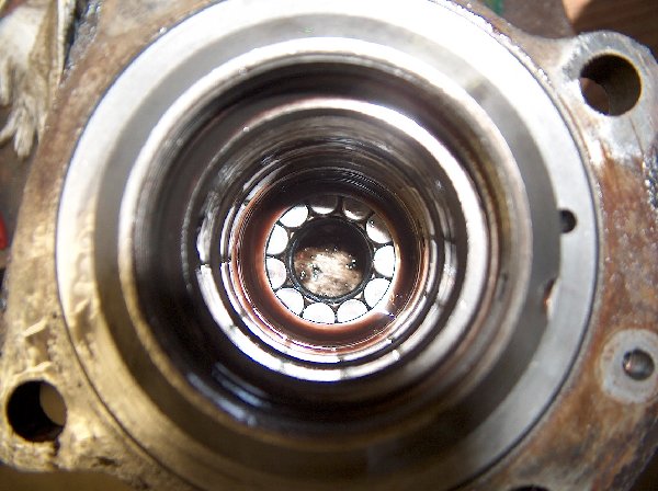
Looking down into the Valve Housing. This pic shows the bearing that the Worm Drive rides on.
Step 17: Remove the dust seal from the bottom of the housing.
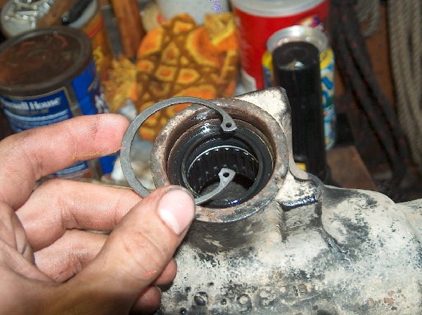
Step 18: Remove the snap-ring. Hard to tell in the pic, but its in there!
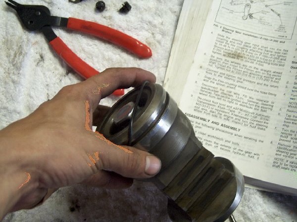
Pic of the snap-ring removed from the housing.
Step 19: With the snap-ring removed, you are free to hammer out the old bearing and oil seal. This seal is the reason I began this project in the first place!
Pic of the dust seal, snap-ring, bearing and oil seal.
Look at that mess of parts!
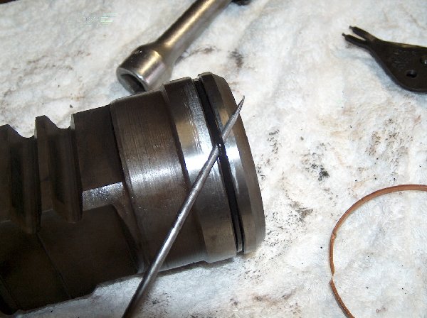
Step 20: Remove the flat Teflon seal from the end of the piston.
Step 21: Remove the O-ring that was hidden directly underneath the Teflon seal (in the same slot of the piston) Both of these will be replaced later.
Step 22: Cut old Teflon seals on the Worm Drive.
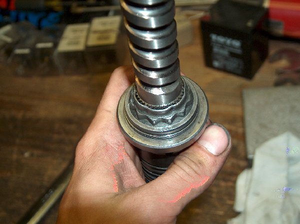
Step 23: This is a 12-point nut. If I recall correctly, it is about 1 5/16″. This needs to be removed so you can replace the spacer/roller thing behind it. The threads are locking threads, with hatching in them so the nut doesn’t back off. Unfortunately, I did not have the tool to remove this, and even with a huge wrench and vise could not bust it loose. Since the roller would spin as if it was brand new, I opted to just continue on and skip this part.
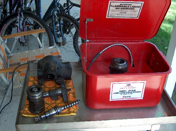
Step 24: (optional) Have parts washer, will wash parts!
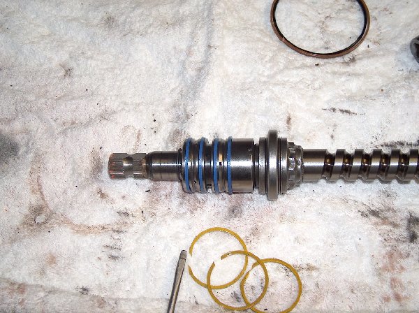
Step 25: Install new Teflon seals on the Worm Drive.
Step 26: Install new O-ring on Piston.
Step 27: Install new Teflon seal over top of O-ring on Piston.
Step 28: Install new bearing in Valve Housing.
Step 29: Install new oil seal. Do not seat the seal directly up against the bearing or it wont seal properly. Instead, set it in so that it is just past the groove for the snap-ring.
Step 30: Install new snap-ring.
Make sure it is fully seated!
Step 31: Install new dust seal.
The Valve Housing is now complete and ready to be re-installed!
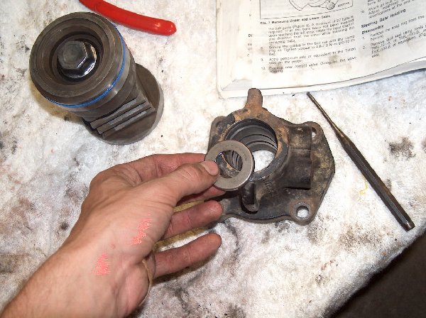
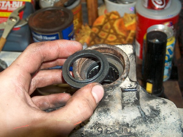
Step 32: Back to the main box housing. Install the new roller bearing with the flat edge up against the seat inside the housing.
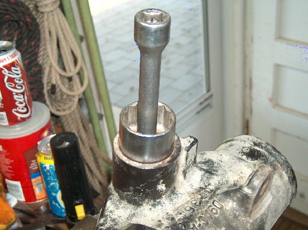
This is a pic of my high-tech bearing-seating-tool. Note the socket is backwards so that it gets better contact with the bearing.
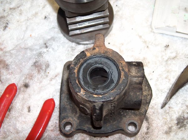
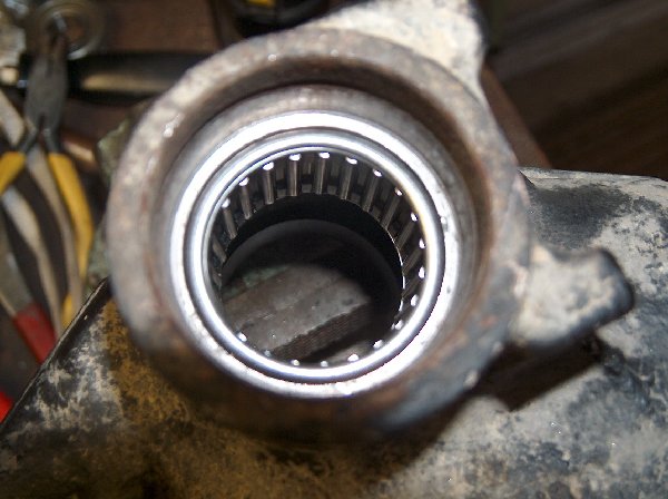
Pic of the bearing fully seated.
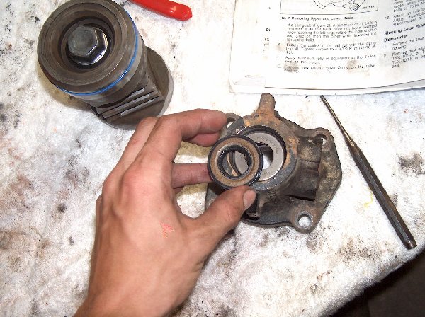
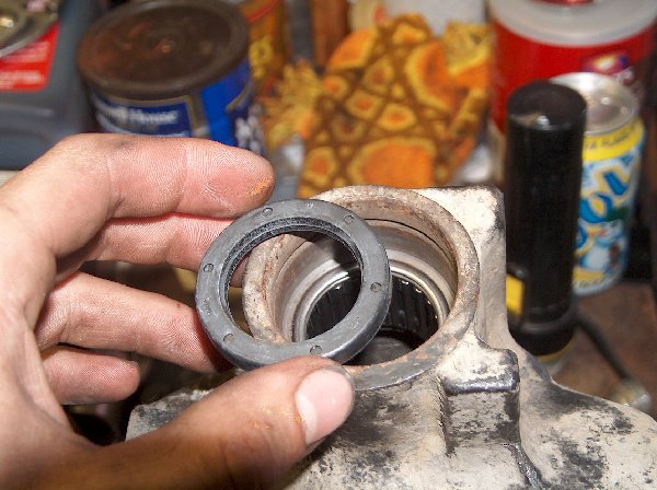
Step 33: Install new oil seal. Again, do not seat the seal directly against the bearing.
Step 34: Install new dust seal.
Step 35: Install new snap-ring.
The housing is now ready to have the Sector Shaft re-installed.
Step 36: Re-install Worm Drive into Valve Housing.
Step 37: Re-install Worm Bearing Race Nut.
Step 38: Install new (flat) seal.
Step 39: Re-install Race Nut Set Screw.
Step 40: Slide Piston over Worm Drive.
Step 41: This is where it gets fun. Rotate the Piston until the holes that the bearings pass through line up with the track in the Worm Drive.
Step 42: Put both Ball Guide halves back in place, and start slipping ball bearings through the hole in the Ball Guide halves. Rotate the Worm Drive back and forth until all the bearings are inside the assembly. This will not work unless you install the Ball Guides before you put any of the bearings in. Trust me, I tried. Several times.
Step 43: Re-install the clamp that holds the Ball Guide halves in place.
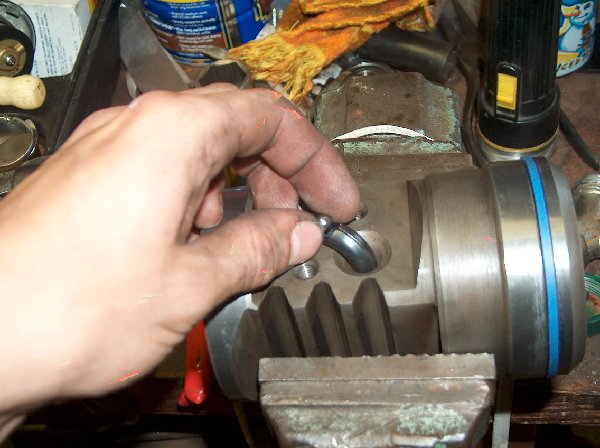
Step 44: Install new O-ring into the appropriate hole on the main Box housing.
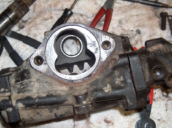
Step 45: Take Worm and Valve Housing Assembly and reinstall it into the housing. Now this part is kind of tricky. The ‘teeth’ on the piston must be facing in the proper direction so that they will mesh with the teeth on the Sector Shaft.
This pic shows how the Piston must be oriented inside the housing. If you don’t put it in like this, the Sector Shaft will not go back into the housing. If you rotate the Worm Drive from lock to lock, and find its center, the teeth will be in the middle, and the Sector Shaft will be able to key into them.
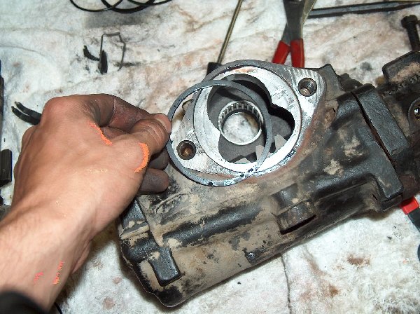
Step 46: Install new flat seal on surface of housing where the Sector Shaft is installed.
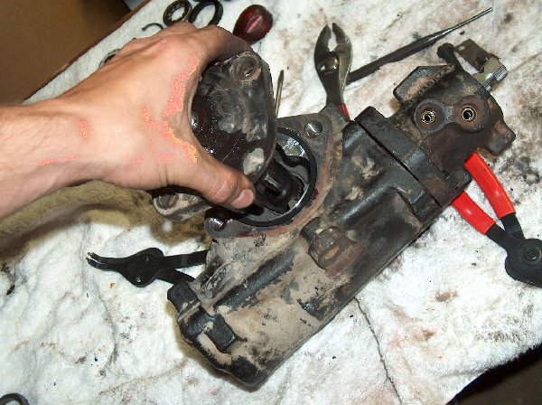
Step 46: Re-install Sector Shaft.
Step 47: Re-install the two bolts that hold the Sector Shaft plate on.
Step 48: This one was for me, but you might not need to do this. At this point you’re basically done. Turn the input shaft and check for backlash. If there is ALOT, you can loosen this nut and turn the screw in in half-turn increments to snug it up, but remember that you do need a certain amount of backlash in there. In most cases (99%), this should not be adjusted at all.
Well, that’s basically it! Now you can re-install the steering box in your truck!
Reconnect the shaft and pressure lines, add some fluid to the power steering pump, and turn on the truck! Let it idle for a second or two, turn it off, add more fluid to the pump, and turn it back on. Crank the wheel a couple times, turn it off, and check the fluid level again. Repeat this as necessary until the fluid level in the pump no longer decreases.
Congratulations! You just rebuilt your steering box
Resource: HERE (page wasn’t visible so we preserved it)

