

Technical Service Bulletin
TSB 23-2062 1999-2023 Ford Ranger Crew Cab – Folding Rear Seat Backrest Assembly Excessive Latching Effort When Returning To The Upright Position
Summary:
This article supersedes TSB 22-2026 to update the vehicle model years affected.
Issue:
Some 2019-2023 Ranger crew cab vehicles may exhibit excessive latching effort when returning the rear seat backrest assembly to the upright position. This may be due to oversized rear seat backrest bumpers preventing latch to striker engagement. Vehicles built on or before 04-Feb-2019 may also have excessive deadening material inside the rear seat backrest latch. To correct this condition, follow the Service Procedure to replace the rear seat backrest bumpers and adjust the striker position.
Action:
Follow the Service Procedure to correct the condition on vehicles that meet all of the following criteria:
2019-2023 Ford Ranger Crew cab
Excessive latching effort when returning the rear seat backrest assembly to the upright position
Parts:
- (1) KB3Z-9961383-A – Rear Seat Back Latch
- (3) KB3Z-2161082-B – Bumper
- (1) W504694-S424 – Screw
- (As Needed) – String – 2-Foot (60 Cm) Long
- (As Needed) – Modeling Clay
Warranty Status:
Eligible under provisions of New Vehicle Limited Warranty (NVLW)/Service Part Warranty (SPW)/Service Part New Vehicle (SPNV)/Extended Service Plan (ESP) coverage. Limits/policies/prior approvals are not altered by a TSB. NVLW/SPW/SPNV/ESP coverage limits are determined by the identified causal part and verified using the OASIS part coverage tool.
Labor Times:
2019-2023 Ranger Crew Cab: Replace And Adjust Backrest Bumpers Following The Service Procedure (Do Not Use With Any Other Labor Operations) – / Operation 232062A / 0.4 Hours
2019-2023 Ranger Crew Cab: Replace The Rear Seat Backrest Latch And Bumpers Includes Time To Adjust Backrest Bumpers Following The Service Procedure (Do Not Use With Any Other Labor Operations) / Operation 232062B / 0.5 Hours
Repair/Claim Coding:
Causal Part: 9961383 / Condition Code: 42
Service Procedure:
1. Check the vehicle build date. Was the vehicle built on or before 04-Feb-2019?
(1). Yes – proceed to Step 2.
(2). No – proceed to Step 14.
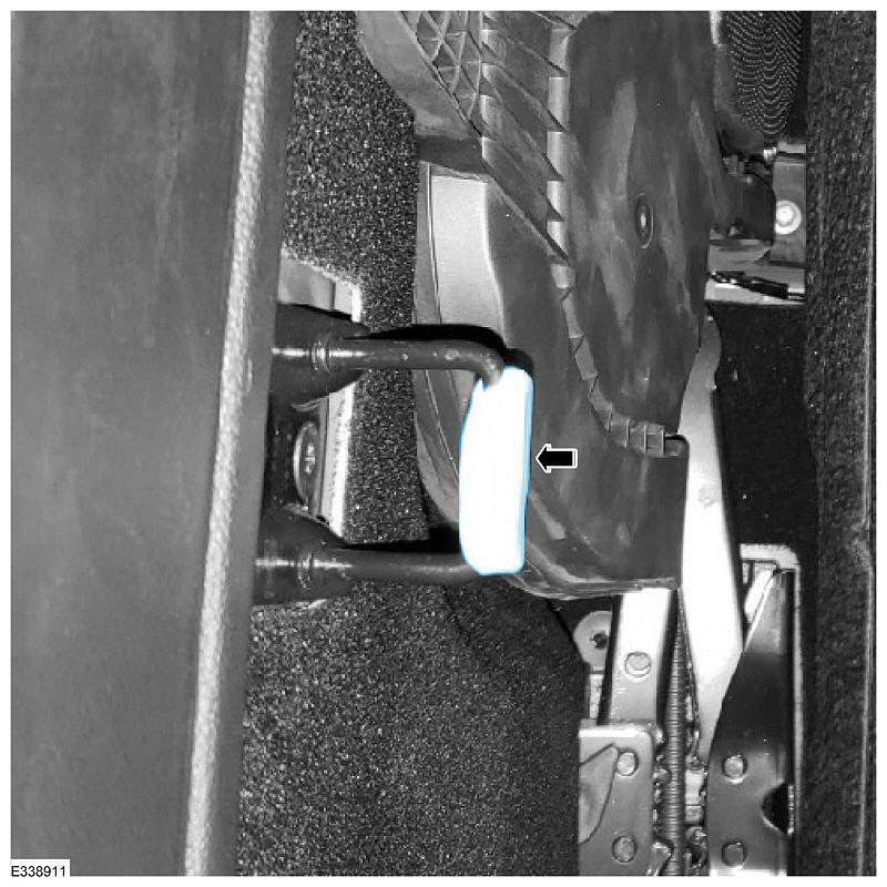
2. Release the rear seat backrest latch (Figure 1 Callout 1) and lower to the fold flat position. (Figure 1 Callout 2)
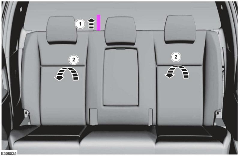
(Figure 1)
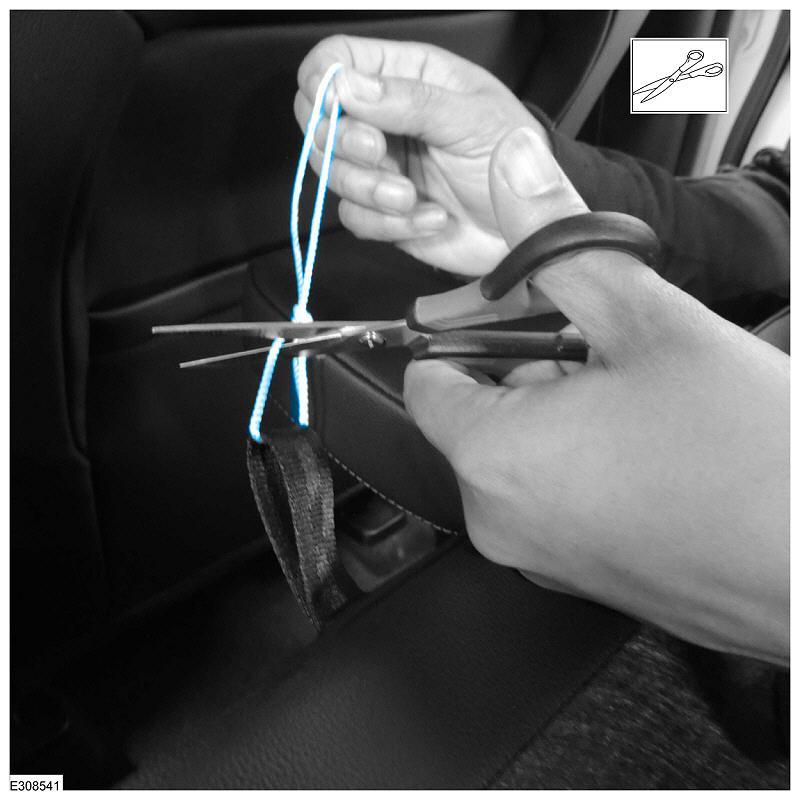
3. Measure and cut a 2-foot (60 cm) piece of string. (Figure 2)
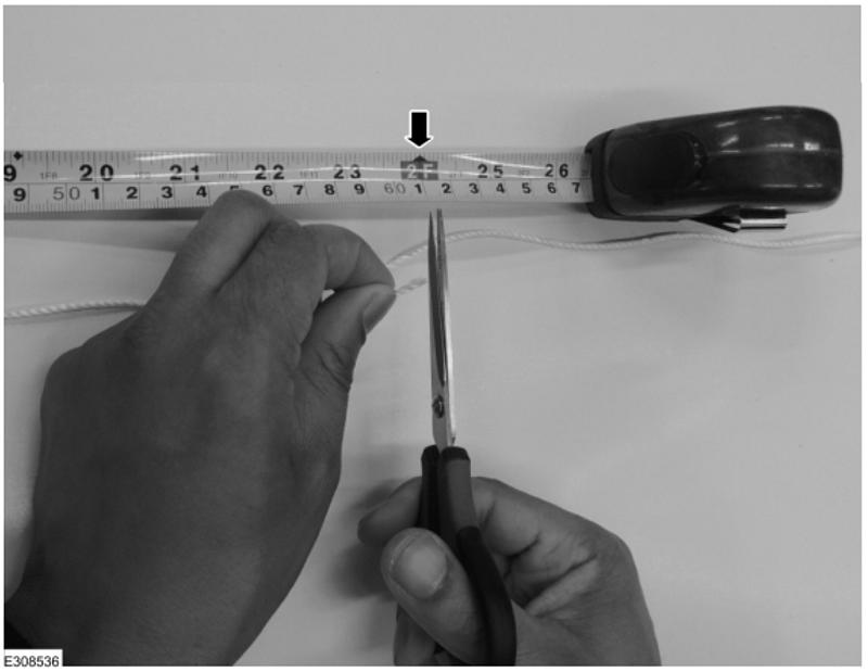
(Figure 2)
CAUTION: Using metal wire can damage the seat backrest cover. Use string to avoid any damage.
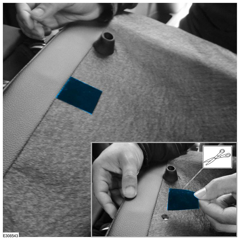
4. Guide the string through the rear seat backrest release strap and double knot a loose loop. (Figure 3)
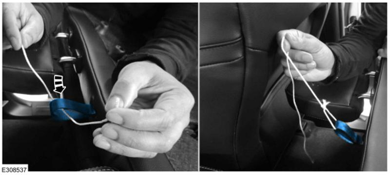
(Figure 3)
5. Remove the rear seat backrest latch retainers. (Figure 4)
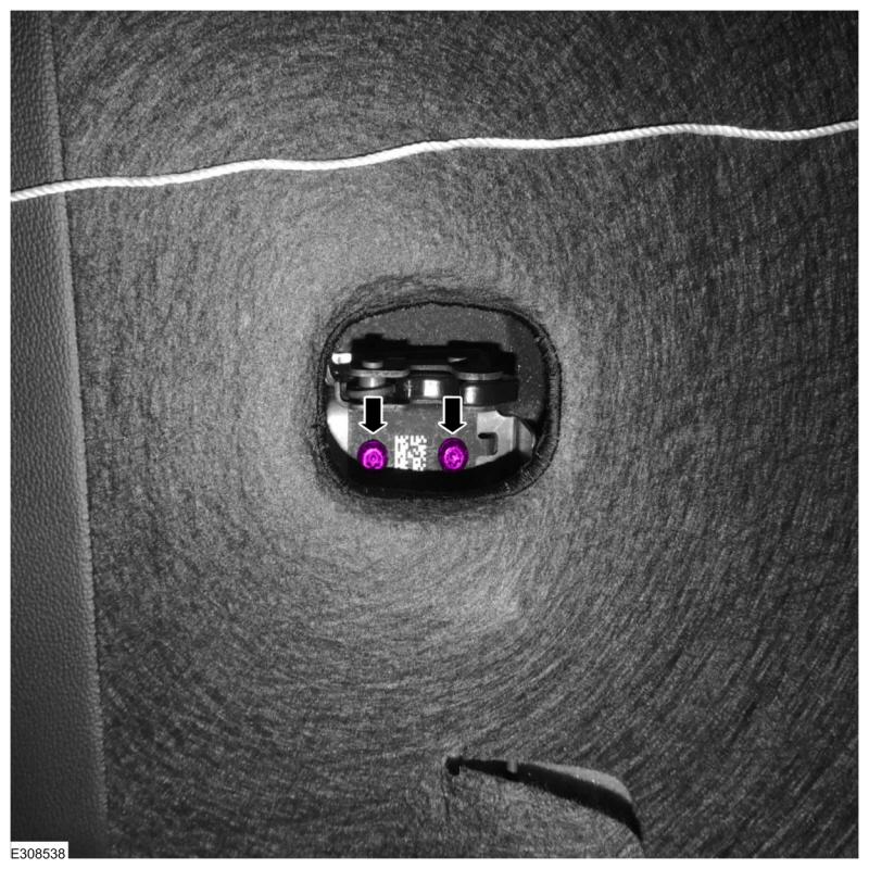
(Figure 4)
6. Holding the string, guide the rear seat backrest latch up and out of the rear seat backrest assembly just enough to access and remove the rear seat backrest latch release strap. (Figure 5)
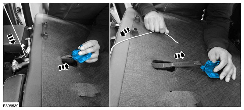
(Figure 5)
7. Remove and discard the rear seat backrest latch from the rear seat backrest release strap. (Figure 6)
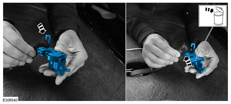
(Figure 6)
8. Install the rear seat backrest release strap onto the new rear seat backrest latch.
9. Install the new rear seat backrest latch by pulling the string attached to the rear seat backrest release strap back through the seat backrest cover and guiding the rear seat backrest latch back into the rear seat backrest assembly. (Figure 5)
10. Install the rear seat backrest latch retainers. (Figure 4)
(1). Tighten both retainers to 1.2 Nm (10.6 in-lb).
11. Remove the string attached to the rear seat backrest release strap. (Figure 7) Make sure to cut the string as far away from the rear seat backrest release strap as possible or damage to the release strap may occur.
(Figure 7)
12. Remove and discard the passenger side inboard rear seat backrest bumper on the backside of the rear seat backrest assembly. (Figure 8)
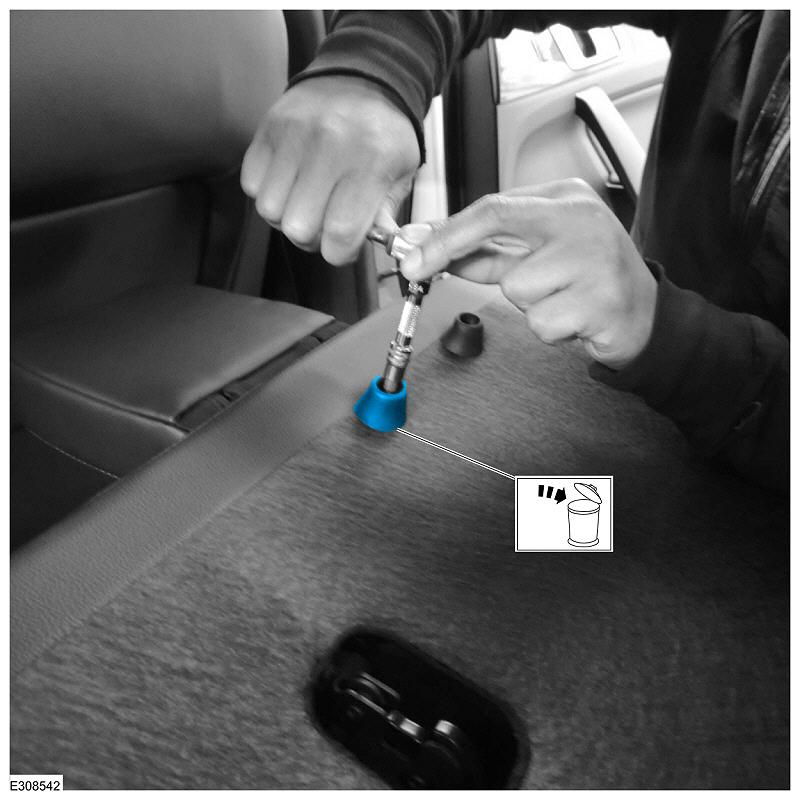
(Figure 8)
13. Cut a 1.5 inch by 1.5 inch (40 mm by 40 mm) piece of flock tape and install it over the rear seat backrest bumper retainer hole. (Figure 9)
(Figure 9)
14. Remove only the rear seat outermost head restraints.
(1). Press inward on the head restraint locks.
(2). Lift upward on the head restraint.
15. Replace all 3 rear seat backrest bumpers and fasteners. Tighten to 1.6 Nm (14 lb-in)
16. Perform a drag test using a sheet of paper to determine which of the 3 rear seat backrest bumpers contacts the back of the cab first.
(1). While covering one rear seat backrest bumper with a sheet of paper, raise the rear seat backrest so it is in the upright position, but not latched, and lightly tug on the paper to determine if that bumper is contacting the rear of the cab. Repeat this test on all 3 bumpers.
(2). The rear seat backrest bumper that holds the paper will be considered rear seat backrest bumper X. Remember the location of rear seat backrest bumper X, as it will be used later in the procedure. (Figure 10)
NOTE: If more than one seat backrest bumper is found to be contacting the rear of the cab, the bumper closest to the latch should be considered rear seat backrest bumper X.
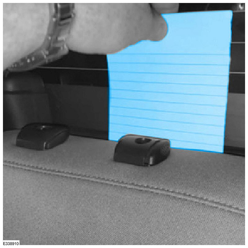
(Figure 10)
17. Use modeling clay to measure the position of the rear seat back rest latch relative to the striker.
(1). With the rear seat backrest assembly folded to the flat position, apply modeling clay to the width of the striker. The modeling clay should be no more than 5mm thick on the forward side of the striker. (Figure 11)
(2). While holding a sheet of paper over rear seat backrest bumper X, raise the rear seat backrest assembly until vertical.
(3). Allow gravity to pull the rear seat backrest assembly the rest of the way against the modeling clay while lightly tugging on the paper to confirm when the rear seat backrest bumper X is against the cab. If the paper is not being held, apply very light pressure near rear seat backrest bumper X until resistance can be felt when tugging on the paper.
(Figure 11)
NOTE: Applying too much pressure against the rear seat backrest may compress the rear seat backrest bumpers and give a false impression in the modeling clay.
18. Lower the rear seat backrest assembly to the fold flat position and inspect the impression in the modeling clay left by the rear seat backrest latch. Is the striker visible through the modeling clay? (Figure 12)
(1). Yes – no adjustments to the rear seat backrest bumpers are necessary, however, material may be removed from the rubber bumpers to reduce seat latching efforts for customer preference, but removing too much material may result in rear seat backrest noise, vibration, and harshness (NVH) concerns.
(2). No – proceed to Step 19.
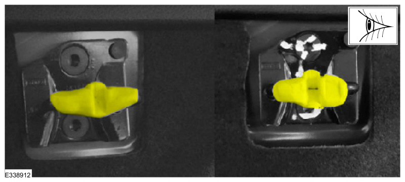
(Figure 12)
19. Using a knife or blade, cut away half of the modeling clay through the center of the impression to show a cross section of the impression left by the rear seat backrest latch. (Figure 13)
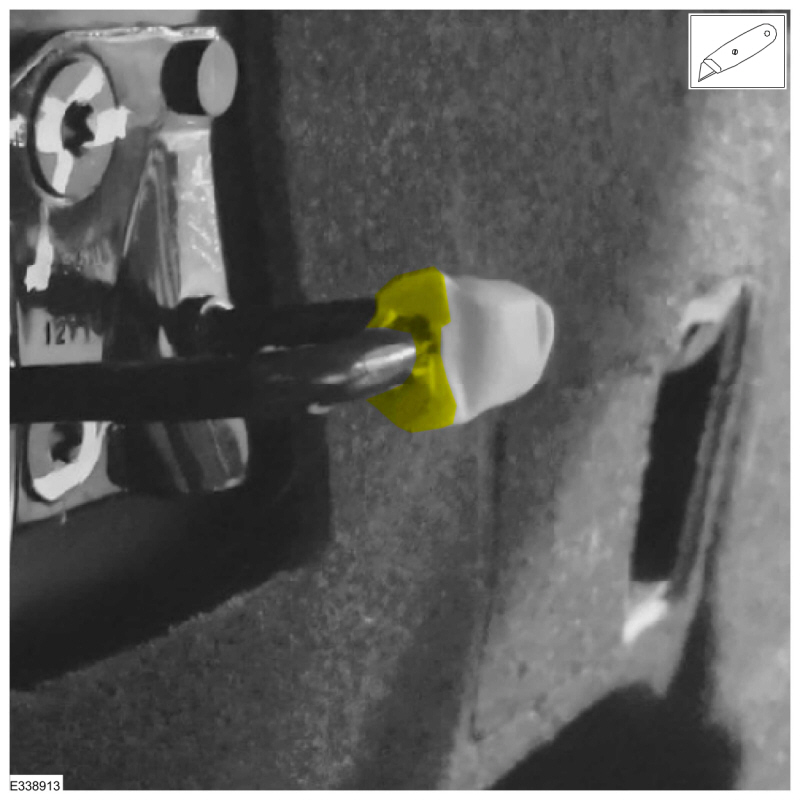
(Figure 13)
20. Using a ruler or dial caliper, measure the distance between the striker and the deepest part of the impression left in the modeling clay by the rear seat backrest latch. This measurement will be how much material is to be removed from each rear seat backrest bumper. (Figure 14)
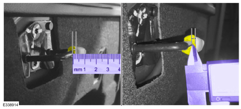
(Figure 14)
21. Per the modeling clay measurement, mark the top of each rear seat backrest bumper in 4 places, 90° apart, to indicate the amount of material to be removed.
22. Using sandpaper or sanding block (80 grit is preferred), remove the measured amount of material from each rear seat backrest bumper. Make sure that any shavings are cleaned prior to returning the vehicle to the customer.
NOTE: The amount of material removed when using this measuring process should allow for reasonable latching efforts without creating any NVH related issues. Additional material may be removed to further reduce seat latching efforts for customer preference but removing too much material may result in rear seat backrest NVH concerns.
23. Remove all modeling clay from the striker.
24. Raise and latch the rear seat backrest assembly.
25. Install the rear seat outermost head restraints.
NOTE: The information in Technical Service Bulletins is intended for use by trained, professional technicians with the knowledge, tools, and equipment to do the job properly and safely. It informs these technicians of conditions that may occur on some vehicles, or provides information that could assist in proper vehicle service. The procedures should not be performed by “do-it-yourselfers”. Do not assume that a condition described affects your car or truck. Contact a Ford or Lincoln dealership to determine whether the Bulletin applies to your vehicle. Warranty Policy and Extended Service Plan documentation determine Warranty and/or Extended Service Plan coverage unless stated otherwise in the TSB article. The information in this Technical Service Bulletin (TSB) was current at the time of printing. Ford Motor Company reserves the right to supersede this information with updates. The most recent information is available through Ford Motor Company’s on-line technical resources.