|
|
||||||||||||||
|
|
||||||||||||||
|
|
|
By 'Dishtowel'
The Lincoln's (Ford) 5.0L V-8 This
wiring guide is derived from my experience installing a Ford 5.0L EFI
engine from a Lincoln Town Car into a 1986 Ford Bronco II that had a 2.9L
V-6. That is what this specifically applies to, but I believe that it will work with
any Ranger or Bronco II that had the 2.9L.
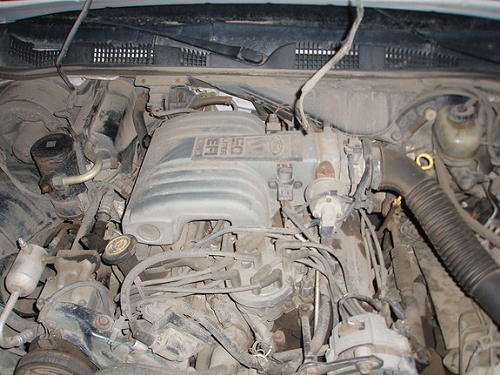
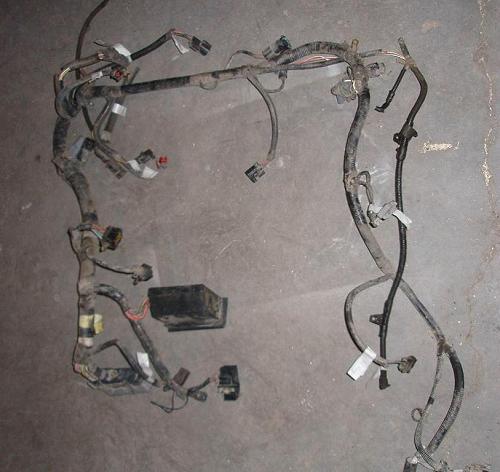
(5.0L Main Harness) Once you have installed the engine and are happy with it’s position and have installed the harness from the car you are ready to button up wiring. Not far from the computer connector is a Black Square, 16-pin connector:
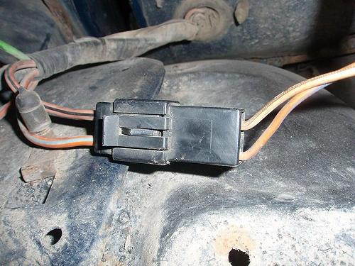
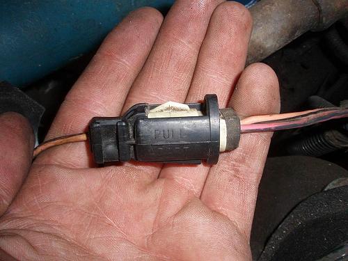
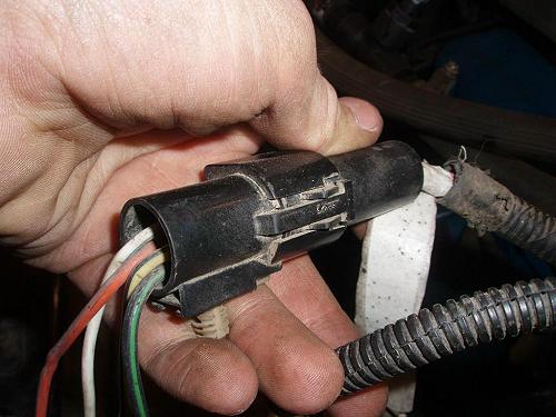
(Black Square 16-Pin Connector) 1) Red/Yellow = Control to fuel pump relay. Must go through the Ranger/Bronco II inertia switch and connect to Solid Red (#4). The inertia switch is by the passenger left foot, it has Pink/Black & Orange/Blue wires. It’s connector in the engine bay is a Black Rectangular 2-Pin. (Inertia switch connector pictured)
(Inertia Switch Connector) 2) Yellow/Blue = Vehicle speed sensor for cruise control, not used. 3) Tan/Green = VIP (?) connection, not used. 4) Red = Connect to #1 wire (Red/Yellow) through the inertia switch. 5) Red/White = Unknown, not used. 6) Pink/White = Unknown, not used. 7) Pink/Purple = VIP (?) feed, not used. 8) White/Red = Oil pressure warning light. 9) *Black + 2 Blue stripes = GROUND 10) Tan/Red = Check engine light 11) *Blue + 2 Black stripes = Speed Control sensor, not used. 12) Red/Dark Green = This wire is HOT when starting, (resultant). Not used. 13) Green/Orange = Cruise control, not used. 14) Blue/Green = This wire went to the instrument panel, not used. 15) Pink/Black = Big power from fuel pump relay to Ranger/Bronco II harness and into Ranger/Bronco II fuel pump. Connect to Orange/Black wire that goes into Black/Grey/White Round 1-Pin connector. (Connector pictured)
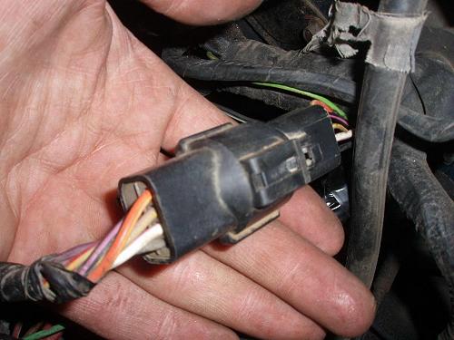
(Black/Grey/White Round 1- Pin Connector) 16) Green/White = Anti-Lock brakes, unused On the 5.0L harness there is a Black Round/Rectangular 8-pin, 7-wire connector:
(Black Round/Rectangular 8-Pin, 7-Wire Connector) 1) Black = Connect to a big fat Red wire from a Grey Rectangular 8-pin connector on the Ranger/Bronco II.
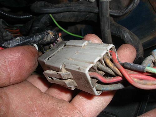
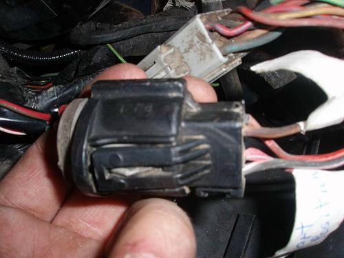
(Grey Rectangular 8-Pin Connector) 2) White/Pink = Connect to Red/Light Blue (Start position on Key) from Black/Grey Round 4-pin connector on Ranger/Bronco II. (Pictured)
(Black/Grey Round 4-Pin Connector) 3) Tan/Yellow = Unknown, not used. 4) Orange/Yellow = Connect to Purple/Orange (Run position on key) from Black/Grey Round 4 pin connector on Ranger/Bronco II. 5) Purple = MAF sensor to EEC (not used because I used a Speed Density motor/computer combo) 6) Red/Yellow = Unknown, not used. 7) Black/Pink = Unknown, not used. At the opposite end of the harness from the computer there a Black Round 4-pin connector.
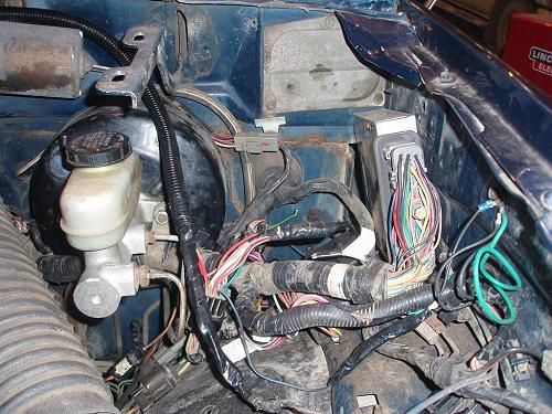
(Black Round 4-Pin Connector) 1) Black/Green = GROUND 2) Orange/Blue = Always hot, 20 Amp fuse. 3) Yellow/Black = Always hot, 30 Amp fuse. 4) White/Blue = Starter Solenoid/Relay signal wire. This is the wire that tells your starter to engage. There is a two pin connector that splices out of the Neutral Safety Switch loom down with the transmission. This goes to your vehicle speed sensor, which is piggy-backed on your speed-O gear. This just transmits a frequency, so which-wire-to-which-wire does not matter. I just cut into my existing wires going from the VSS to the 2.9 computer and attached them to the wires going to the 2 pin connector. This tells the computer that the vehicle is in fact moving. You can run without this hooked up, but it may lead to stalling when you snap the throttle closed under load, or coming to a stop with an automatic. I was able to tidy all my wiring into one neat corner with the computer. I have yet to secure (and hopefully make water resistant) the computer yet, but that is about where mine will live. I ran the 60 pin, relay box, and the other connecter in-between the brake master cylinder and above the brake lines coming from it.
Other Notes: •MAKE SURE TO WELL GROUND ALL GROUND WIRES, THIS IS THE MOST LIKELY CAUSE OF FAILURE. •Make sure Grey/Light Blue on the 60 pin computer connector is well grounded. •Make sure you have good connection on your 60 pin connector. I suffered from an erratic computer my first week because not all pins were making contact. My ohm meter pin is slightly bigger than the female side of the connector and they where all stretched a tiny bit. I went in and crimped them with o-ring pliers. 100% now. •This answer key is derived assuming you have a working and plugged in Neutral Safety Switch. The start signal goes from the key through the NSS, then to the starter. Do not hotwire the NSS this is one of the most dangerous things you could do. Especially if someone besides you ever has to drive this vehicle. (Which will eventually happen.)
|
|
|