97RangerXLT
Forum Staff Member
TRS Forum Moderator
Article Contributor
TRS 20th Anniversary
TRS Event Participant
TRS 25th Anniversary
- Joined
- Sep 18, 2007
- Messages
- 6,819
- Reaction score
- 3,996
- Points
- 113
- Location
- Fishers, IN
- Vehicle Year
- 1997
- Make / Model
- Ford
- Engine Type
- 4.0 V6
- Engine Size
- 4.0
- Transmission
- Automatic
- 2WD / 4WD
- 4WD
- Total Lift
- 2"
- Tire Size
- 31"
Resurrecting your A/C

Its summer and your A/C does not work. That sucks. Well, I have the write up to help you get it back on the road. Keep in mind, my write up only covers 134a systems, specifically in the 1997 4.0 OHV configuration. I believe that 94+ Rangers were outfitted with R134a, but 94 was a transition year, so you might have either R12 or R134a for that year. The overall advice given will apply to other engines and years as well, but you might have to make some adjustments mechanically.
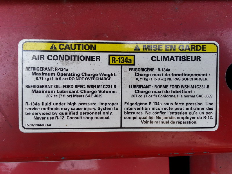
Difficulty: 9 out of 10 wrenches. The reason I am putting this so high is that you really need to pay attention to details. Miss a detail and you can have all of your work be for nothing, including trashing a very expensive compressor. Another difficulty is that messing with the refrigerant cans is dangerous. If you open the wrong valves on the manifold gauge set you can cause the can to explode, possibly severely injuring yourself or any bystanders. Also, keep in mind that the different years of Rangers use different amounts of refrigerant. The 97 has 25 ounces which is a hair over two 12 ounce cans, where the 94 uses 28 ounces (although I have seen 36 ounces for the 94 as well, but I believe that might be for the R12 version) the 1999 uses 30 ounces. This information will also be displayed on the sticker that is on top of the radiator support. Go with that amount if the sticker is still there and readable. I highly recommend that you read this How-To in its entirety before you start the repair, and make sure that you understand each step and what and why you are doing it. If you are unsure of something, ask someone who is knowledgeable, or take your truck to a shop.
Before job preparations:
Remove children, small animals, anyone with sensitive ears and anyone else that you do not want to be a target of your frustration and anger toward the Ford engineers that designed this cussing mess…
Disclaimer:
The Ranger Station.com, The Ranger Station.com Staff, nor the original poster are responsible for you doing this modification to your vehicle. By doing this modification and following this how-to you, the installer, take full responsibility if anything is damaged or messed up. If you have questions, feel free to PM the original poster or ask in the appropriate section of The Ranger Station.com forums.
Lets Look at how your A/C works:
Before we get to the testing and repair, let’s look briefly at how an air conditioner works. An air conditioner has 5 main parts: The compressor, Evaporator (in the heater box) Condenser (in front of the radiator), Accumulator/dryer (right next to the heater box in the engine compartment) and expansion valve or orifice tube. The engine is what runs the compressor. If there is enough static pressure (the pressure in the system when the A/C is not running) which is over 75 psi, and the electromagnetic clutch is working, when you turn on the A/C, the clutch will engage the compressor which pressurizes the Refrigerant gas. This in turn makes the Refrigerant gas very hot (basic thermodynamics). This hot Refrigerant then goes into the condenser which extracts the heat from the refrigerant using the trucks radiator fan or as the air goes across the condenser when the truck is moving, causing the Refrigerant to condense into a liquid. After the liquid Refrigerant exits the condenser, it goes through the expansion valve or orifice tube into the Low-Pressure side of the system where the Refrigerant starts boiling rapidly as it goes into the evaporator. This boiling causes the liquid Refrigerant inside the evaporator to get very cold as it turns back into a gas (again, basic thermodynamics), and a fan blows over the evaporator which cools the air and because cooler air also cannot hold as much moisture, causes the moisture in the air to condense into water which lowers the humidity of the air as well. After the evaporator the Refrigerant gas goes into the accumulator/dryer. The accumulator/dryer holds excess PAG oil, removes any moisture in the refrigerant using a desiccant and catches any liquid refrigerant that has not boiled into gas yet (Liquid refrigerant going into the compressor will hydro lock it, just like taking water in the intake of the truck). The gas then returns to the compressor to start the cycle all over again. The compressor clutch is controlled by the use of the pressure transducer switches. If the pressure gets too high, the High side transducer (located on the manifold bolted to the back of the compressor) will open and not allow the power to the clutch until the pressure drops back down. The pressure switch transducer which is located on the accumulator/ dryer is open if there is not enough static pressure. If there is enough static pressure, the clutch will engage. You may now wake up, the boring lecture is over.
*Note for those doing a R12 to R134a Retrofit: you will need to replace your hoses, o-rings, and all of the oil. You want to be very careful of what oil you use, as some will not be compatible with the old mineral oil that the R12 systems use! I will not cover retrofitting in this walk through in detail. Also note, if your truck is not a 97, research the capacities for the oil and refrigerant before starting, and make adjustments to these instructions to fit your particular truck.
A word or two about Refrigerants and Oils: I am only doing this walk through for the 94+ trucks that have the R134a refrigerant. If you are looking to do a retrofit as R12 is now illegal to buy or sell, (at least for the average consumer that does not have a proper license to buy and sell R12) you will want to do some more research on what parts you need to replace and how much refrigerant to use, what type of oil to use etc. R134a is a fairly inexpensive refrigerant. You can get it at just about any department store or automotive store from about 7 to 10 dollars for a 12 oz can. Do not use anything but R134a, as other refrigerants can be incompatible with the oil and cause a big mess. Plus, any car that has a refrigerant blend or any weird or exotic refrigerants will not be touched by any mechanic as the recovery process will contaminate his machine and supply of R134a. It is also illegal to knowingly vent the refrigerant into the atmosphere. It must be recovered by a qualified person who has the recovery equipment.
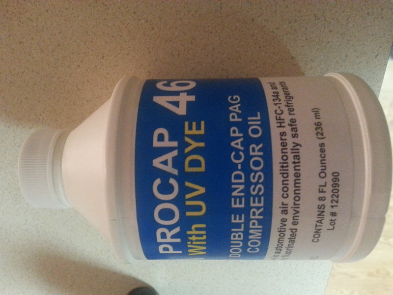
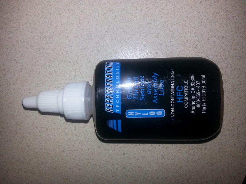
For oil, Ford uses PAG 46 in most of its R134a systems. I recommend getting the Double End Capped PAG 46, as it has much better lubricating qualities than regular PAG 46, plus the Double End Capped PAG oil does not absorb moisture. PAG 100 or PAG 150 are too thick. It is not very much more expensive, and for what you are paying to replace the compressor if getting new, it is worth the 2 or 3 bucks extra. I also got some special oil for the o-rings and fittings called Nylog. It is specifically designed to keep the o-rings pliable and prevent leaks.
A Quick tip: before doing any work on the A/C, make sure all electrical connections (connector at the compressor, and the connector at the pressure switches), fuses and relays are good. Also check the blend doors in the dash, as this is a trouble spot for the Ranger. If any of these are bad, the A/C will not come on or will not work right. Also make sure the belt tensioner is working properly. Check the condenser to see if the fins need cleaning and / or straightening. If your condenser has all of the fins bent over you will have reduced airflow through the condenser and that will decrease the effectiveness of your A/C. You can get a fin comb from Harbor Freight for 5 bucks.
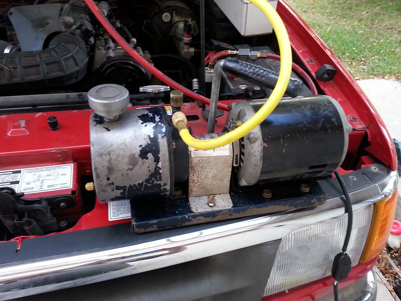
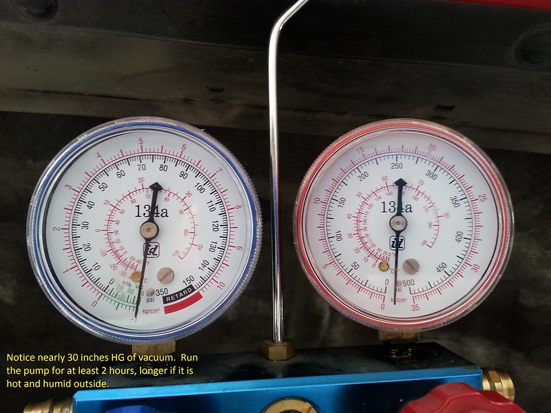
Tools: You will need access to some special tools for this fix. You will need an A/C manifold gauge set, and a vacuum pump to evacuate the system. You can buy the manifold gauge set at AutoZone or O’Reilly for about $90 or Harbor Freight for about $50. The pump is quite abit more expensive. I recommend borrowing or renting one for this, but Craigslist can be a source as well. I picked mine up on Craigslist for $35. Another option is the Harbor Freight vacuum pump that hooks up to your shop air compressor. This is only $20, but it will not pull a deep vacuum like a regular vacuum pump made for refrigeration will. *note, if using the Harbor freight vacuum pump that attaches to your air compressor, make sure your compressor can maintain at least 110 psi continually for the time that you are using it. Most home compressors do not have this capacity, so if you do not have a commercial compressor, you might be better off buying a used a/c vacuum pump. Also running an air compressor for an extended period of time will consume a lot of electricity, so be aware of that when you get your energy bill. If you are doing the air compressor vacuum route, I also recommend starting and warming the truck up before pulling the vacuum. The residual heat from the engine will help boil out the moisture at a much faster rate. If you warm up the truck before pulling the vacuum you can shorten the amount of time with the vacuum pump turned on. An hour or so should do the trick. (Thanks 4x4 Junkie!)
Other tools needed:
• 27mm wrench
• 22mm wrench
• 13mm socket and ratchet
• 11mm deep well socket
• 10mm wrench
• 8mm wrench
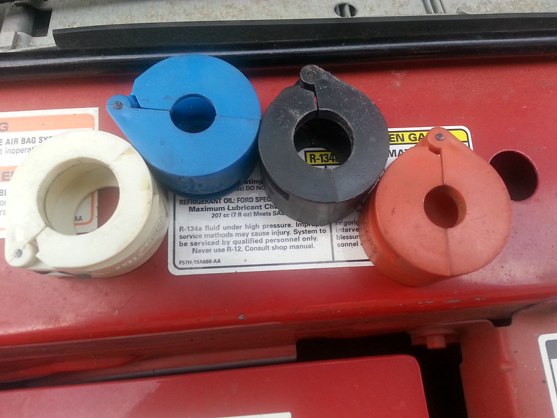
• A/C – Fuel line disconnect tools (3 different sizes)
• Digital Thermometer
• Feeler gauge set
• A pick to help remove old o-rings and springlocks
• Orifice Tube Puller
• A/C flush kit which has a bottle that can be pressurized with flush solvent and air and a hose and spray gun. I bought this off of Amazon for about $45
• Four Seasons Dura II Flush Solvent – Expensive at $32 a quart, but this stuff is the best flush compound you can get. You can also use Turpentine as a flush. I bought a quart of Turpentine to do the initial clean and flush, and then used the Four Seasons stuff as the final flush.
• A length of hose that fits over the evaporator outlet and condenser outlet to direct the flush solvent into a catch can.
• Catch can for the flush solvent.
I am going to write this in sections. Each section will be devoted to a specific part that is being replaced. This way you can go to the section you need to fix a specific area of the air conditioning system. At the end will be the Appendixes that will give you some troubleshooting tips and how to flush and charge the system.
For the component replacement sections keep this important fact in mind: If you do any component replacement other than the pressure transducer switches or the clutch, (ie opening the system) you will need to replace the accumulator/dryer. If you open the system to the air for more than a few minutes you must replace the accumulator/dryer. In fact, on a very humid day, a brand new accumulator/ dryer can fill with moisture in as little as 15 minutes, rendering the desiccant inside useless. If your system is good, but all of the Refrigerant has leaked out, you must replace the accumulator/dryer. The reason for this is that the accumulator/dryer is what removes moisture from the Refrigerant. This prevents ice or the water from forming an acidic compound inside your A/C lines and trashing your compressor/ condenser/ evaporator. The good news is that this accumulator/dryer is only about $25 at AutoZone.
Parts: I bought most of my parts from Rockauto.com. Overall, I spent about $500 in parts. I basically replaced everything but the evaporator, condenser, and the pressure switches. If you are opening the system for whatever reason, you will need to replace the accumulator/ dryer and the orifice tube. Another rule of thumb, if you unhook something with an o-ring, replace the o-ring before you put it back together. They are cheap, and it would suck to have to pull the unit apart again after you get it back together and charged up only to find the old o-rings are bad. If you are replacing the compressor, to have the warranty honored, you will have to show proof of purchase of an accumulator/ dryer, orifice tube, and condenser or have the old condenser flushed. It only takes a few teaspoons of the gunk from the old compressor that is in the lines to wreck the new compressor.
For the cheap minded, I recommend the local junkyard, especially those of you who have access to a u pull yard. I picked up a compressor for under 20 dollars with a 30 day warranty at the local Pull A Part in Indy for my 94 Intrepid a few years ago. The car that you yank your parts from should have no serious front end damage, and I would get a part from a car that has some refrigerant charge left in it. This will tell you the system is intact. For compressors, make sure that the pulley spins freely and that you can turn the compressor with a good firm grip on the hub of the pulley. You will hear it pumping and it should have a little resistance or stiffness in it. What not to get in the yard? The accumulator/dryer and orifice tube. The accumulator/dryer is $25 at AutoZone and the orifice tube is 2 bucks. Both need to be replaced with new anytime you open the system.
Here is the list of parts that I bought to get my Ranger ice cold again:
• Compressor
• Accumulator/ dryer
• Orifice tube
• Refrigerant Line – suction and high pressure with High pressure port (big one that goes from the compressor around the back of the engine to the top of the accumulator/ dryer)
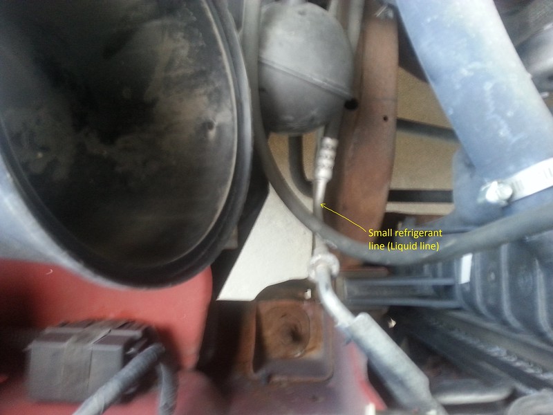
• Refrigerant line – liquid (little one from the condenser to the evaporator)
• O-ring kit (all the new parts that I bought had new o-rings/ springlocks installed, but in case I messed one up…)
Now for the work.
• Section 1 – Pressure switches
• Section 2 – Electromagnetic clutch and pulley
• Section 3 – Accumulator/ Dryer
• Section 4 – Orifice tube
• Section 5 – Compressor
• Section 6 – Large refrigerant line (suction and high side port from compressor to accumulator/ dryer)
• Section 7 – Small refrigerant line (liquid – from condenser to evaporator)
• Section 8 – Condenser
• Appendix A – Flushing the system
• Appendix B – Prepping a new system for a charge
• Appendix C – Charging the system
• Appendix D – Troubleshooting
• Appendix E – Sources
Parts replacement: The first thing you need to do in all instances except replacing the pressure transducer switch and replacing the electromagnetic clutch is to have the system evacuated of refrigerant. Remember, it is illegal to knowingly vent any refrigerant into the atmosphere, so if there is a charge left in the system, have it properly reclaimed.
Section 1
Part to be replaced: Pressure switch transducer (High and Low).
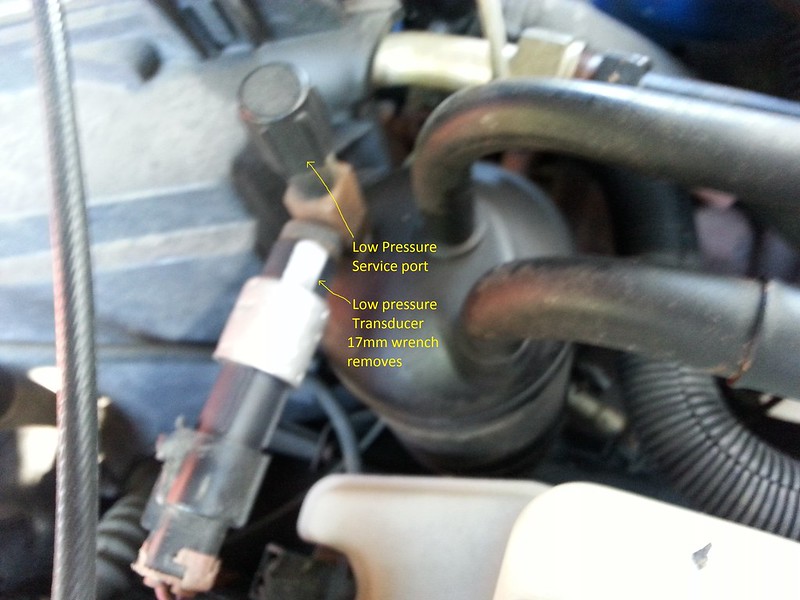
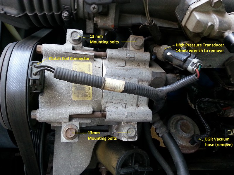
Located on the accumulator/dryer for the low pressure transducer, and right off of the back of the compressor for the High pressure transducer. These parts can be easily accessed from the top of the engine and removed with an appropriate size wrench. These are one of two parts in this section that you do not need to evacuate the system to replace. You need to unplug the wire harness from it and you will need a 17mm open end wrench to remove the low pressure transducer and a 14mm open end wrench to remove the high pressure transducer. Both transducers have an o-ring, be sure to replace the o-ring and coat it with Nylog or PAG oil before putting the new transducer on.
Section 2
Part to be replaced: Electromagnetic clutch.
This is the other part that does not require evacuating the system.
Tools you will need:
• Safety glasses
• 8mm socket or wrench
• 13mm socket
• Flat blade screwdriver
• Ratchet
• Set of feeler gauges
• 15mm combination wrench
• Torque wrench
• Snap ring pliers
• Plastic or soft face hammer
• Three jaw puller or A/C clutch tool
Procedure:
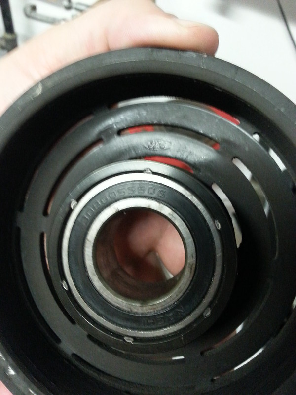
1. If you are replacing the bearing only, here is the part number from the OEM ford bearing: Nachi 30BG05S5DS
2. Remove the serpentine belt. This is done by placing a 3/8” breaker bar in the tensioner (located in the middle of the engine) and using it to take the tension off of the belt.
3. Disconnect the wire to the electromagnetic clutch.
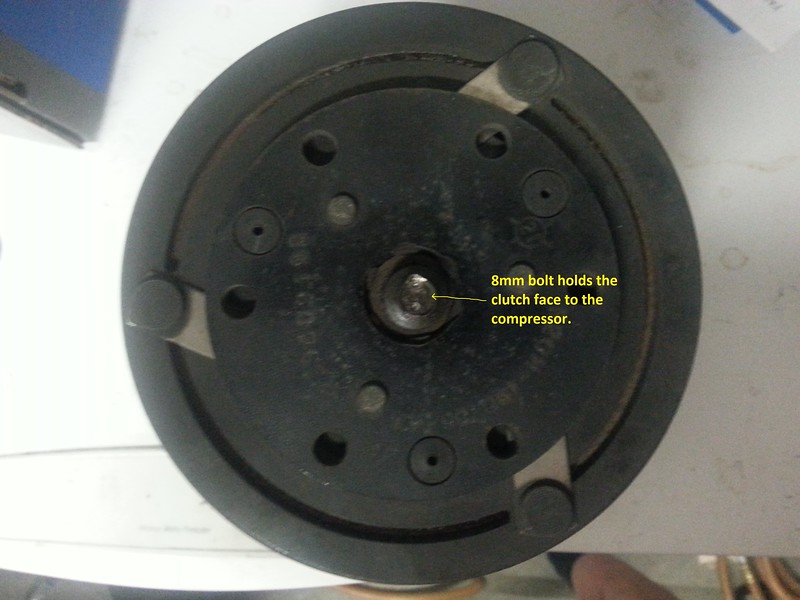
4. Remove the center bolt from the hub of the clutch assembly (8 mm) you will have to snap the wrench or ratchet quickly to keep the compressor shaft from turning while doing this. You can also get a spanner wrench to hold the compressor from turning.
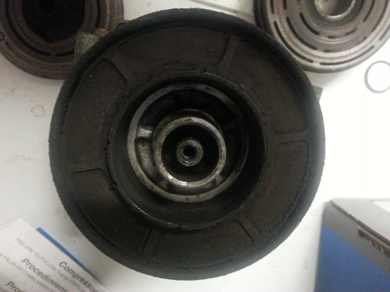
5. Gently tap the screwdriver between the clutch plate and pulley with the hammer at several intervals around the clutch plate to remove the clutch plate and shim(s).
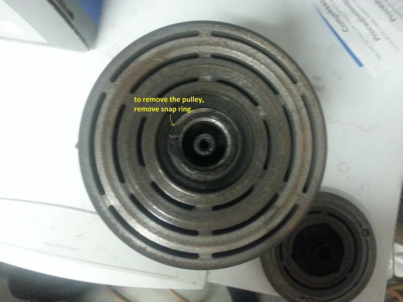
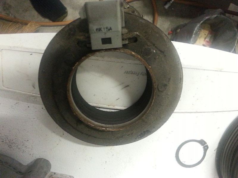
6. Remove the pulley and bearing assembly by removing the snap ring holding it on.
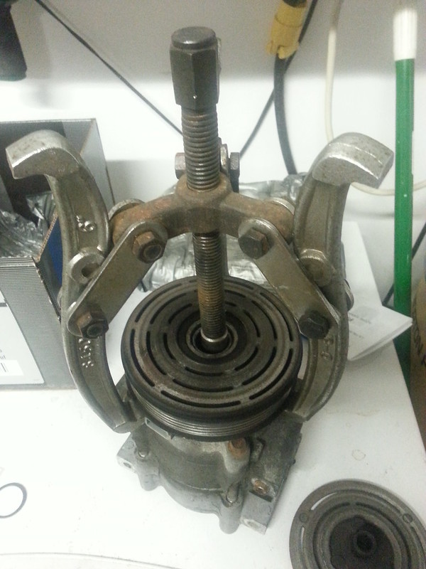
7. You will also need a three jaw puller or clutch puller tool to assist in removing the pulley assembly. Be careful when setting the jaw on the puller so that you do not damage the electrical connector to the coil. For replacing the bearing, you can remove just the pulley and not the coil if you set the jaws out far enough to just grip the pulley, but the coil is also pressed onto the shaft and will need a puller to remove. The coil is really pressed in hard and will need quite a bit of work to pull off. I do not recommend removing the coil if you just need to replace the pulley, bearing or clutch plate.
8. If there is oil all over the clutch from the compressor shaft, your life just got uglier. See replacing of compressor below. (You technically do not have to replace the compressor, just the seal to the shaft. And that requires removing the compressor…)
9. To install the clutch, if using the same clutch, installation is the reverse of removal. Be sure to align the socket for the power connector in the coil so that it is on top of the connector and sitting in the notch of the compressor housing. You will need to press the coil onto the shaft. A large socket will help seat the coil. Use the rubber hammer to set the pulley back on the shaft.
10. Installing a new clutch assembly or pulley will require you to set the movement distance (air gap) between the plate and the pulley face when the clutch is energized. This movement distance must be between .013” and .033” as measured with a feeler gauge.
11. If the distance between the clutch plate and pulley is outside of the minimum and maximum clearances, you will need to add or remove shims to get it into spec.
12. Torque the center bolt to 12 ft. lbs.

For the rest of these parts, you will need to evacuate the system and replace the accumulator/dryer as well. To evacuate a charged system, take the car to a shop and have them reclaim the refrigerant as it is illegal, immoral, and probably fattening to vent it into the air. If you do not have any charge to the system, all the easier for you Whatever you do, make sure that you do not try *any* of the below repairs until you are absolutely 100% sure that the system has no charge or pressure in it!! And always wear safety glasses when dealing with the A/C system!
Section 3.
Part to be replaced: Accumulator/ dryer
Located by the heater box on the passenger side
Tools and parts needed:
• Safety glasses
• A/C – Fuel line disconnect tool
• 27mm Combination wrench
• 22mm Combination wrench
• 8mm wrench or socket/ ratchet
• Bottle of PAG 46 DEC oil
• Nylog
• PB blaster
Procedure:
1. Remove the low pressure transducer switch (see Section 1 for details)
2. Soak the nut that is attached to the top tube of the evaporator with PB blaster. Wait a few minutes and soak it again. When you think you have let it soak in enough that you can break it loose, grab the can of PB blaster and hit it again. You might need to repeat this process a few times…
3. Use the 27mm wrench on the nut from the evaporator and the 22mm wrench on the nut for the accumulator. The nut on the accumulator is part of the tube and does *not* turn. It is there so you do not twist the tubing when tightening the nut from the evaporator. Turn the evaporator nut clockwise (as viewed from the front of the truck looking at the firewall. This was a reaaaly tight nut on my truck, with some of the threads showing a fair amount of rust on the accumulator.
4. You may still need to repeat step 1 to get step 2 to work…
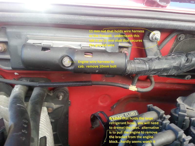
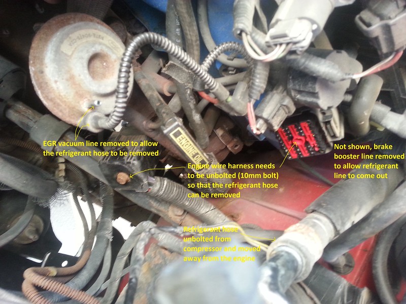
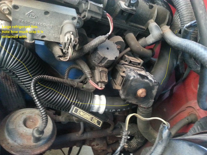
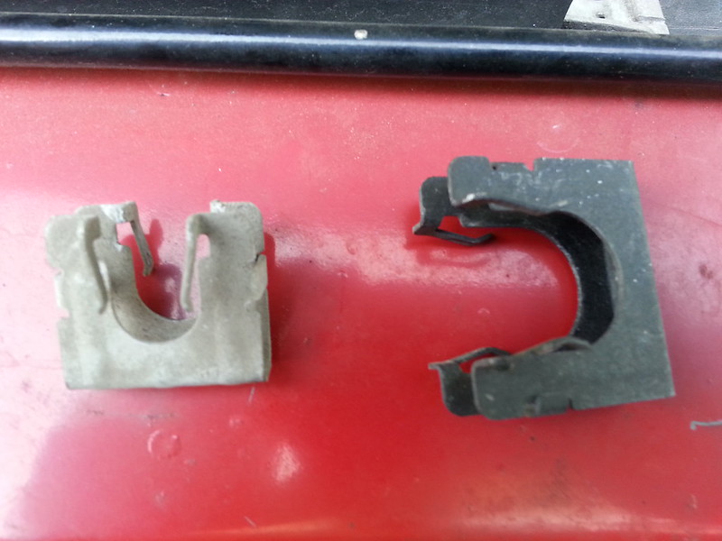
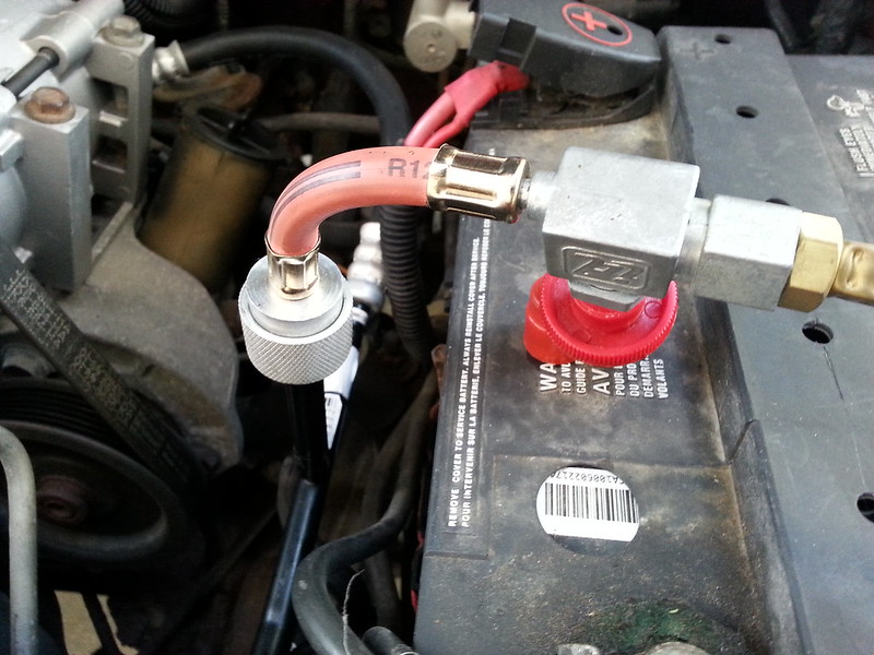
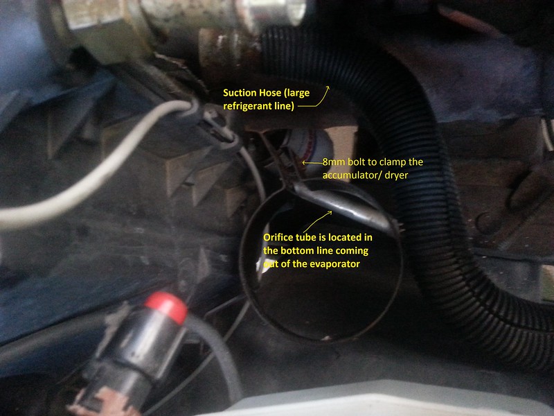
5. Disconnect the large refrigerant line from the other side of the accumulator. (This is the line that goes around the back of the engine and then comes underneath the radiator hose and curls in a “U” up to the accumulator.) You will need the largest disconnect tool (white) to unhook this line. Before you put the disconnect tool on, you will need to remove the metal keeper. This can be removed by using your hands or a gentle pry with a small screw driver. They just slide off of the connection point. It will take a bit to muscle the hose off of the accumulator/ dryer as the o-rings will hold it on pretty tight.
6. Take your 8mm wrench/ socket and remove the 8 mm bolt that holds the bracket to the bottom line coming out of the evaporator. The bracket will swing down out of the way.
7. Take the 8mm wrench/ socket and loosen (you do not need to remove it completely) several turns the bolt that holds the clamp around the accumulator dryer.
8. Slide the accumulator/ dryer up and out of the truck. Make sure your new accumulator/ dryer matches the old one.
9. Pour as much oil out of the old accumulator/ dryer as you can into a container. You will need to put in at least this much new PAG oil into the new Accumulator/ Dryer
10. When you are ready to put the new one in (remember, this is the last step you want to do before sealing and refilling the system so do not break the seals on the new unit until you are ready to seal it up and fill the system) be sure that it has all new o-rings and coat them with Nylog or PAG oil. There will be two o-rings at the evaporator end and two o-rings at the refrigerant line end, plus one o-ring for the low pressure transducer.
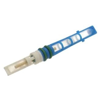
Section 4.
Part to be replaced: Orifice tube
Located in the lower tube coming out of the Evaporator core.
Tools and parts you will need:
• Safety Glasses
• A/C – Fuel line disconnect tool
• Orifice tube removal tool
• Bottle of PAG 46 DEC oil
• Nylog
• New Orifice tube
• New Accumulator/ Dryer
Procedure:
1. Remove Accumulator/ Dryer (see section 3 for details)
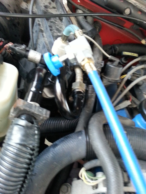
2. Remove the metal keeper and use the second smallest A/C line disconnect tool (blue) and disconnect the short refrigerant line from the bottom line of the evaporator.
3. Use the Orifice tube tool to extract the orifice tube. You can also use a pair of needle nose pliers instead of the Orifice tube tool, but I could not get a grip on the orifice tube with the pliers I had, so rather than fight it for two hours, I went and bought the damn orifice tube tool. Made my life much easier……* Protip: Compressed air can be used to blow the orifice tube out if it is being stubborn. (wish I would have thought of that…Again thanks 4x4 Junkie for that helpful tip)
4. Make sure your new orifice tube matches the old, and pitch the old tube. Don’t bother trying to clean and reuse it, they are only $2.00, it isn’t worth it.
5. Be sure to put some PAG Oil on the o-rings of the new Orifice tube
6. Replace the o-rings and put Nylog or PAG Oil on them when hooking the line back up.
Stay tuned for the next installment..
AJ
Its summer and your A/C does not work. That sucks. Well, I have the write up to help you get it back on the road. Keep in mind, my write up only covers 134a systems, specifically in the 1997 4.0 OHV configuration. I believe that 94+ Rangers were outfitted with R134a, but 94 was a transition year, so you might have either R12 or R134a for that year. The overall advice given will apply to other engines and years as well, but you might have to make some adjustments mechanically.
Difficulty: 9 out of 10 wrenches. The reason I am putting this so high is that you really need to pay attention to details. Miss a detail and you can have all of your work be for nothing, including trashing a very expensive compressor. Another difficulty is that messing with the refrigerant cans is dangerous. If you open the wrong valves on the manifold gauge set you can cause the can to explode, possibly severely injuring yourself or any bystanders. Also, keep in mind that the different years of Rangers use different amounts of refrigerant. The 97 has 25 ounces which is a hair over two 12 ounce cans, where the 94 uses 28 ounces (although I have seen 36 ounces for the 94 as well, but I believe that might be for the R12 version) the 1999 uses 30 ounces. This information will also be displayed on the sticker that is on top of the radiator support. Go with that amount if the sticker is still there and readable. I highly recommend that you read this How-To in its entirety before you start the repair, and make sure that you understand each step and what and why you are doing it. If you are unsure of something, ask someone who is knowledgeable, or take your truck to a shop.
Before job preparations:
Remove children, small animals, anyone with sensitive ears and anyone else that you do not want to be a target of your frustration and anger toward the Ford engineers that designed this cussing mess…
Disclaimer:
The Ranger Station.com, The Ranger Station.com Staff, nor the original poster are responsible for you doing this modification to your vehicle. By doing this modification and following this how-to you, the installer, take full responsibility if anything is damaged or messed up. If you have questions, feel free to PM the original poster or ask in the appropriate section of The Ranger Station.com forums.
Lets Look at how your A/C works:
Before we get to the testing and repair, let’s look briefly at how an air conditioner works. An air conditioner has 5 main parts: The compressor, Evaporator (in the heater box) Condenser (in front of the radiator), Accumulator/dryer (right next to the heater box in the engine compartment) and expansion valve or orifice tube. The engine is what runs the compressor. If there is enough static pressure (the pressure in the system when the A/C is not running) which is over 75 psi, and the electromagnetic clutch is working, when you turn on the A/C, the clutch will engage the compressor which pressurizes the Refrigerant gas. This in turn makes the Refrigerant gas very hot (basic thermodynamics). This hot Refrigerant then goes into the condenser which extracts the heat from the refrigerant using the trucks radiator fan or as the air goes across the condenser when the truck is moving, causing the Refrigerant to condense into a liquid. After the liquid Refrigerant exits the condenser, it goes through the expansion valve or orifice tube into the Low-Pressure side of the system where the Refrigerant starts boiling rapidly as it goes into the evaporator. This boiling causes the liquid Refrigerant inside the evaporator to get very cold as it turns back into a gas (again, basic thermodynamics), and a fan blows over the evaporator which cools the air and because cooler air also cannot hold as much moisture, causes the moisture in the air to condense into water which lowers the humidity of the air as well. After the evaporator the Refrigerant gas goes into the accumulator/dryer. The accumulator/dryer holds excess PAG oil, removes any moisture in the refrigerant using a desiccant and catches any liquid refrigerant that has not boiled into gas yet (Liquid refrigerant going into the compressor will hydro lock it, just like taking water in the intake of the truck). The gas then returns to the compressor to start the cycle all over again. The compressor clutch is controlled by the use of the pressure transducer switches. If the pressure gets too high, the High side transducer (located on the manifold bolted to the back of the compressor) will open and not allow the power to the clutch until the pressure drops back down. The pressure switch transducer which is located on the accumulator/ dryer is open if there is not enough static pressure. If there is enough static pressure, the clutch will engage. You may now wake up, the boring lecture is over.
*Note for those doing a R12 to R134a Retrofit: you will need to replace your hoses, o-rings, and all of the oil. You want to be very careful of what oil you use, as some will not be compatible with the old mineral oil that the R12 systems use! I will not cover retrofitting in this walk through in detail. Also note, if your truck is not a 97, research the capacities for the oil and refrigerant before starting, and make adjustments to these instructions to fit your particular truck.
A word or two about Refrigerants and Oils: I am only doing this walk through for the 94+ trucks that have the R134a refrigerant. If you are looking to do a retrofit as R12 is now illegal to buy or sell, (at least for the average consumer that does not have a proper license to buy and sell R12) you will want to do some more research on what parts you need to replace and how much refrigerant to use, what type of oil to use etc. R134a is a fairly inexpensive refrigerant. You can get it at just about any department store or automotive store from about 7 to 10 dollars for a 12 oz can. Do not use anything but R134a, as other refrigerants can be incompatible with the oil and cause a big mess. Plus, any car that has a refrigerant blend or any weird or exotic refrigerants will not be touched by any mechanic as the recovery process will contaminate his machine and supply of R134a. It is also illegal to knowingly vent the refrigerant into the atmosphere. It must be recovered by a qualified person who has the recovery equipment.
For oil, Ford uses PAG 46 in most of its R134a systems. I recommend getting the Double End Capped PAG 46, as it has much better lubricating qualities than regular PAG 46, plus the Double End Capped PAG oil does not absorb moisture. PAG 100 or PAG 150 are too thick. It is not very much more expensive, and for what you are paying to replace the compressor if getting new, it is worth the 2 or 3 bucks extra. I also got some special oil for the o-rings and fittings called Nylog. It is specifically designed to keep the o-rings pliable and prevent leaks.
A Quick tip: before doing any work on the A/C, make sure all electrical connections (connector at the compressor, and the connector at the pressure switches), fuses and relays are good. Also check the blend doors in the dash, as this is a trouble spot for the Ranger. If any of these are bad, the A/C will not come on or will not work right. Also make sure the belt tensioner is working properly. Check the condenser to see if the fins need cleaning and / or straightening. If your condenser has all of the fins bent over you will have reduced airflow through the condenser and that will decrease the effectiveness of your A/C. You can get a fin comb from Harbor Freight for 5 bucks.
Tools: You will need access to some special tools for this fix. You will need an A/C manifold gauge set, and a vacuum pump to evacuate the system. You can buy the manifold gauge set at AutoZone or O’Reilly for about $90 or Harbor Freight for about $50. The pump is quite abit more expensive. I recommend borrowing or renting one for this, but Craigslist can be a source as well. I picked mine up on Craigslist for $35. Another option is the Harbor Freight vacuum pump that hooks up to your shop air compressor. This is only $20, but it will not pull a deep vacuum like a regular vacuum pump made for refrigeration will. *note, if using the Harbor freight vacuum pump that attaches to your air compressor, make sure your compressor can maintain at least 110 psi continually for the time that you are using it. Most home compressors do not have this capacity, so if you do not have a commercial compressor, you might be better off buying a used a/c vacuum pump. Also running an air compressor for an extended period of time will consume a lot of electricity, so be aware of that when you get your energy bill. If you are doing the air compressor vacuum route, I also recommend starting and warming the truck up before pulling the vacuum. The residual heat from the engine will help boil out the moisture at a much faster rate. If you warm up the truck before pulling the vacuum you can shorten the amount of time with the vacuum pump turned on. An hour or so should do the trick. (Thanks 4x4 Junkie!)
Other tools needed:
• 27mm wrench
• 22mm wrench
• 13mm socket and ratchet
• 11mm deep well socket
• 10mm wrench
• 8mm wrench
• A/C – Fuel line disconnect tools (3 different sizes)
• Digital Thermometer
• Feeler gauge set
• A pick to help remove old o-rings and springlocks
• Orifice Tube Puller
• A/C flush kit which has a bottle that can be pressurized with flush solvent and air and a hose and spray gun. I bought this off of Amazon for about $45
• Four Seasons Dura II Flush Solvent – Expensive at $32 a quart, but this stuff is the best flush compound you can get. You can also use Turpentine as a flush. I bought a quart of Turpentine to do the initial clean and flush, and then used the Four Seasons stuff as the final flush.
• A length of hose that fits over the evaporator outlet and condenser outlet to direct the flush solvent into a catch can.
• Catch can for the flush solvent.
I am going to write this in sections. Each section will be devoted to a specific part that is being replaced. This way you can go to the section you need to fix a specific area of the air conditioning system. At the end will be the Appendixes that will give you some troubleshooting tips and how to flush and charge the system.
For the component replacement sections keep this important fact in mind: If you do any component replacement other than the pressure transducer switches or the clutch, (ie opening the system) you will need to replace the accumulator/dryer. If you open the system to the air for more than a few minutes you must replace the accumulator/dryer. In fact, on a very humid day, a brand new accumulator/ dryer can fill with moisture in as little as 15 minutes, rendering the desiccant inside useless. If your system is good, but all of the Refrigerant has leaked out, you must replace the accumulator/dryer. The reason for this is that the accumulator/dryer is what removes moisture from the Refrigerant. This prevents ice or the water from forming an acidic compound inside your A/C lines and trashing your compressor/ condenser/ evaporator. The good news is that this accumulator/dryer is only about $25 at AutoZone.
Parts: I bought most of my parts from Rockauto.com. Overall, I spent about $500 in parts. I basically replaced everything but the evaporator, condenser, and the pressure switches. If you are opening the system for whatever reason, you will need to replace the accumulator/ dryer and the orifice tube. Another rule of thumb, if you unhook something with an o-ring, replace the o-ring before you put it back together. They are cheap, and it would suck to have to pull the unit apart again after you get it back together and charged up only to find the old o-rings are bad. If you are replacing the compressor, to have the warranty honored, you will have to show proof of purchase of an accumulator/ dryer, orifice tube, and condenser or have the old condenser flushed. It only takes a few teaspoons of the gunk from the old compressor that is in the lines to wreck the new compressor.
For the cheap minded, I recommend the local junkyard, especially those of you who have access to a u pull yard. I picked up a compressor for under 20 dollars with a 30 day warranty at the local Pull A Part in Indy for my 94 Intrepid a few years ago. The car that you yank your parts from should have no serious front end damage, and I would get a part from a car that has some refrigerant charge left in it. This will tell you the system is intact. For compressors, make sure that the pulley spins freely and that you can turn the compressor with a good firm grip on the hub of the pulley. You will hear it pumping and it should have a little resistance or stiffness in it. What not to get in the yard? The accumulator/dryer and orifice tube. The accumulator/dryer is $25 at AutoZone and the orifice tube is 2 bucks. Both need to be replaced with new anytime you open the system.
Here is the list of parts that I bought to get my Ranger ice cold again:
• Compressor
• Accumulator/ dryer
• Orifice tube
• Refrigerant Line – suction and high pressure with High pressure port (big one that goes from the compressor around the back of the engine to the top of the accumulator/ dryer)
• Refrigerant line – liquid (little one from the condenser to the evaporator)
• O-ring kit (all the new parts that I bought had new o-rings/ springlocks installed, but in case I messed one up…)
Now for the work.
• Section 1 – Pressure switches
• Section 2 – Electromagnetic clutch and pulley
• Section 3 – Accumulator/ Dryer
• Section 4 – Orifice tube
• Section 5 – Compressor
• Section 6 – Large refrigerant line (suction and high side port from compressor to accumulator/ dryer)
• Section 7 – Small refrigerant line (liquid – from condenser to evaporator)
• Section 8 – Condenser
• Appendix A – Flushing the system
• Appendix B – Prepping a new system for a charge
• Appendix C – Charging the system
• Appendix D – Troubleshooting
• Appendix E – Sources
Parts replacement: The first thing you need to do in all instances except replacing the pressure transducer switch and replacing the electromagnetic clutch is to have the system evacuated of refrigerant. Remember, it is illegal to knowingly vent any refrigerant into the atmosphere, so if there is a charge left in the system, have it properly reclaimed.
Section 1
Part to be replaced: Pressure switch transducer (High and Low).
Located on the accumulator/dryer for the low pressure transducer, and right off of the back of the compressor for the High pressure transducer. These parts can be easily accessed from the top of the engine and removed with an appropriate size wrench. These are one of two parts in this section that you do not need to evacuate the system to replace. You need to unplug the wire harness from it and you will need a 17mm open end wrench to remove the low pressure transducer and a 14mm open end wrench to remove the high pressure transducer. Both transducers have an o-ring, be sure to replace the o-ring and coat it with Nylog or PAG oil before putting the new transducer on.
Section 2
Part to be replaced: Electromagnetic clutch.
This is the other part that does not require evacuating the system.
Tools you will need:
• Safety glasses
• 8mm socket or wrench
• 13mm socket
• Flat blade screwdriver
• Ratchet
• Set of feeler gauges
• 15mm combination wrench
• Torque wrench
• Snap ring pliers
• Plastic or soft face hammer
• Three jaw puller or A/C clutch tool
Procedure:
1. If you are replacing the bearing only, here is the part number from the OEM ford bearing: Nachi 30BG05S5DS
2. Remove the serpentine belt. This is done by placing a 3/8” breaker bar in the tensioner (located in the middle of the engine) and using it to take the tension off of the belt.
3. Disconnect the wire to the electromagnetic clutch.
4. Remove the center bolt from the hub of the clutch assembly (8 mm) you will have to snap the wrench or ratchet quickly to keep the compressor shaft from turning while doing this. You can also get a spanner wrench to hold the compressor from turning.
5. Gently tap the screwdriver between the clutch plate and pulley with the hammer at several intervals around the clutch plate to remove the clutch plate and shim(s).
6. Remove the pulley and bearing assembly by removing the snap ring holding it on.
7. You will also need a three jaw puller or clutch puller tool to assist in removing the pulley assembly. Be careful when setting the jaw on the puller so that you do not damage the electrical connector to the coil. For replacing the bearing, you can remove just the pulley and not the coil if you set the jaws out far enough to just grip the pulley, but the coil is also pressed onto the shaft and will need a puller to remove. The coil is really pressed in hard and will need quite a bit of work to pull off. I do not recommend removing the coil if you just need to replace the pulley, bearing or clutch plate.
8. If there is oil all over the clutch from the compressor shaft, your life just got uglier. See replacing of compressor below. (You technically do not have to replace the compressor, just the seal to the shaft. And that requires removing the compressor…)
9. To install the clutch, if using the same clutch, installation is the reverse of removal. Be sure to align the socket for the power connector in the coil so that it is on top of the connector and sitting in the notch of the compressor housing. You will need to press the coil onto the shaft. A large socket will help seat the coil. Use the rubber hammer to set the pulley back on the shaft.
10. Installing a new clutch assembly or pulley will require you to set the movement distance (air gap) between the plate and the pulley face when the clutch is energized. This movement distance must be between .013” and .033” as measured with a feeler gauge.
11. If the distance between the clutch plate and pulley is outside of the minimum and maximum clearances, you will need to add or remove shims to get it into spec.
12. Torque the center bolt to 12 ft. lbs.
For the rest of these parts, you will need to evacuate the system and replace the accumulator/dryer as well. To evacuate a charged system, take the car to a shop and have them reclaim the refrigerant as it is illegal, immoral, and probably fattening to vent it into the air. If you do not have any charge to the system, all the easier for you
Whatever you do, make sure that you do not try *any* of the below repairs until you are absolutely 100% sure that the system has no charge or pressure in it!! And always wear safety glasses when dealing with the A/C system!Section 3.
Part to be replaced: Accumulator/ dryer
Located by the heater box on the passenger side
Tools and parts needed:
• Safety glasses
• A/C – Fuel line disconnect tool
• 27mm Combination wrench
• 22mm Combination wrench
• 8mm wrench or socket/ ratchet
• Bottle of PAG 46 DEC oil
• Nylog
• PB blaster
Procedure:
1. Remove the low pressure transducer switch (see Section 1 for details)
2. Soak the nut that is attached to the top tube of the evaporator with PB blaster. Wait a few minutes and soak it again. When you think you have let it soak in enough that you can break it loose, grab the can of PB blaster and hit it again. You might need to repeat this process a few times…
3. Use the 27mm wrench on the nut from the evaporator and the 22mm wrench on the nut for the accumulator. The nut on the accumulator is part of the tube and does *not* turn. It is there so you do not twist the tubing when tightening the nut from the evaporator. Turn the evaporator nut clockwise (as viewed from the front of the truck looking at the firewall. This was a reaaaly tight nut on my truck, with some of the threads showing a fair amount of rust on the accumulator.
4. You may still need to repeat step 1 to get step 2 to work…
5. Disconnect the large refrigerant line from the other side of the accumulator. (This is the line that goes around the back of the engine and then comes underneath the radiator hose and curls in a “U” up to the accumulator.) You will need the largest disconnect tool (white) to unhook this line. Before you put the disconnect tool on, you will need to remove the metal keeper. This can be removed by using your hands or a gentle pry with a small screw driver. They just slide off of the connection point. It will take a bit to muscle the hose off of the accumulator/ dryer as the o-rings will hold it on pretty tight.
6. Take your 8mm wrench/ socket and remove the 8 mm bolt that holds the bracket to the bottom line coming out of the evaporator. The bracket will swing down out of the way.
7. Take the 8mm wrench/ socket and loosen (you do not need to remove it completely) several turns the bolt that holds the clamp around the accumulator dryer.
8. Slide the accumulator/ dryer up and out of the truck. Make sure your new accumulator/ dryer matches the old one.
9. Pour as much oil out of the old accumulator/ dryer as you can into a container. You will need to put in at least this much new PAG oil into the new Accumulator/ Dryer
10. When you are ready to put the new one in (remember, this is the last step you want to do before sealing and refilling the system so do not break the seals on the new unit until you are ready to seal it up and fill the system) be sure that it has all new o-rings and coat them with Nylog or PAG oil. There will be two o-rings at the evaporator end and two o-rings at the refrigerant line end, plus one o-ring for the low pressure transducer.
Section 4.
Part to be replaced: Orifice tube
Located in the lower tube coming out of the Evaporator core.
Tools and parts you will need:
• Safety Glasses
• A/C – Fuel line disconnect tool
• Orifice tube removal tool
• Bottle of PAG 46 DEC oil
• Nylog
• New Orifice tube
• New Accumulator/ Dryer
Procedure:
1. Remove Accumulator/ Dryer (see section 3 for details)
2. Remove the metal keeper and use the second smallest A/C line disconnect tool (blue) and disconnect the short refrigerant line from the bottom line of the evaporator.
3. Use the Orifice tube tool to extract the orifice tube. You can also use a pair of needle nose pliers instead of the Orifice tube tool, but I could not get a grip on the orifice tube with the pliers I had, so rather than fight it for two hours, I went and bought the damn orifice tube tool. Made my life much easier……* Protip: Compressed air can be used to blow the orifice tube out if it is being stubborn. (wish I would have thought of that…Again thanks 4x4 Junkie for that helpful tip)
4. Make sure your new orifice tube matches the old, and pitch the old tube. Don’t bother trying to clean and reuse it, they are only $2.00, it isn’t worth it.
5. Be sure to put some PAG Oil on the o-rings of the new Orifice tube
6. Replace the o-rings and put Nylog or PAG Oil on them when hooking the line back up.
Stay tuned for the next installment..
AJ
Last edited: