• Welcome Visitor! Please take a few seconds and Register for our forum. Even if you don't want to post, you can still 'Like' and react to posts.

1991 Ranger No Spark


ylidk

Member
Joined
Jul 16, 2018
Messages
52
Reaction score
7
Points
8
Location
KS
Vehicle Year
1991
Make / Model
Ford
Engine Size
2.3l L4
Transmission
Manual
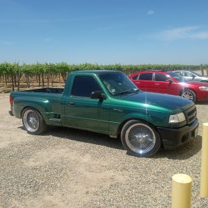
Hey there everyone, I have a 1991 Ranger with the 2.3 L4, RWD, M5R1 transmission. The truck was cheap and didn't run when I bought it, but once I got it running it ran pretty well all things considered.

Recently swapped the head from the 1991 2.3 head, to a spare 2000 2.5 head I had in my garage. The original had compression leaks via the exhaust valve on cylinder 2, and possibly other valves due to lifters that I was able to press down by hand, so I decided to swap the entire head with one that I verified to be good, albeit from a later engine with slightly different flow characteristics.

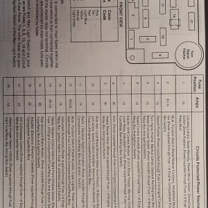
Swap went fine, timing belt lined up fine and the cams were aligned in the same way when I replaced it, yet it ran rough for reasons I could not figure out. When digging around, the red/green wire that leads to the ignition control module / crank pos sensor / noise filters that is hot in run / hot in start grounded against the engine for a brief period of time and fried something. All the fuses checked out, and the relays too, so I began to follow this test procedure:

https://easyautodiagnostics.com/ford/2.3L/icm-and-crank-sensor-tests-1

When following these tests the #1 wire, the red/green wire from before, failed test number one. Not only was the wire not reading 12V between the negative battery post, it read continuity with it, and when I turned the key to "on" it read around 2V. Metering this wire against the positive, with the key off, there was 12V potential, and with the key on it read 10V.

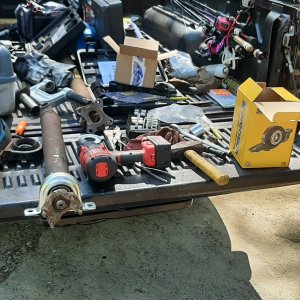
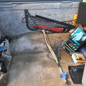
Clearly grounding this wire out caused something weird to happen, whether it melted to a ground wire somewhere that I have yet to find as I have been tearing apart this wiring harness to track down or something else. Disconnecting the engine wiring harness from every plug except for the one this at contains the red/green wire to the main wiring harness. the wire still reads that it is grounded, so it is not the ICM or CKP. If anyone has any ideas or suggestions I appreciate all the help I can get, this issue is killing me.

Thanks in advance!


RonD

Official TRS AI
TRS Technical Advisor
Joined
Jun 2, 2012
Messages
25,363
Reaction score
8,370
Points
113
Location
canada
Vehicle Year
1994
Make / Model
Ford
Transmission
Manual

ylidk

Member
Joined
Jul 16, 2018
Messages
52
Reaction score
7
Points
8
Location
KS
Vehicle Year
1991
Make / Model
Ford
Engine Size
2.3l L4
Transmission
Manual
The red/grn wire at each point shows the same results. The crank sensor was disconnected when checking as well, so the short has to be coming from somewhere else, the only place the wire was connected was at the engine harness to main harness connector with the red/grn wire. I disconnected every other connector on the engine harness to try and isolate it.
 

RonD

Official TRS AI
TRS Technical Advisor
Joined
Jun 2, 2012
Messages
25,363
Reaction score
8,370
Points
113
Location
canada
Vehicle Year
1994
Make / Model
Ford
Transmission
Manual
Don't forget EEC power Relay, it is UNDER the engine fuse box in 1991

Diagram in this thread: https://www.justanswer.com/ford/0pybw-91-ford-ranger-fuel-pump-the-gas-tank-three-times-fuel-relay.html

EEC Relay has a Brown base, Fuel pump relay a Green base, if you have AC then WOT relay has a black base

EEC relay's coil has a full time ground, and red/grn wire is connected to the other side of the coil, so red/grn wire can read as a ground but with 100ohms or so resistance, the coil windings

Unplug the relay to take that off the table
 
Last edited:

ylidk

Member
Joined
Jul 16, 2018
Messages
52
Reaction score
7
Points
8
Location
KS
Vehicle Year
1991
Make / Model
Ford
Engine Size
2.3l L4
Transmission
Manual
Unplugged the relay, no change, however we noticed one of the noise filters was still plugged in and removed that, and the continuity to ground was solved. However, the red wire is not connected to the positive terminal anymore, when the wire grounded a fusible link or something must've blown, does anyone know if there is a fusible link between the red/green wire at the ICM and the positive?
 

RonD

Official TRS AI
TRS Technical Advisor
Joined
Jun 2, 2012
Messages
25,363
Reaction score
8,370
Points
113
Location
canada
Vehicle Year
1994
Make / Model
Ford
Transmission
Manual
Those wires get 12v from the ignition switch, no fuse

But ignition switch's Yellow wires has fuse, in engine fuse box, 40 or 60amp, may be fusible link in 1989

All fusible links are connected to starter relay(solenoid) post with battery positive cable
 

ylidk

Member
Joined
Jul 16, 2018
Messages
52
Reaction score
7
Points
8
Location
KS
Vehicle Year
1991
Make / Model
Ford
Engine Size
2.3l L4
Transmission
Manual
I am now at a loss. Went back out today to continue working on it, and I'm getting the original readings again. 10 volts between the red/grn wire and the positive terminal, 2 volts between the wire and ground, when the key is turned on. Only 100 ohms between the wire and ground at all times. I tried reconnecting the noise capacitor and there was no change to the readings this time.
 

ylidk

Member
Joined
Jul 16, 2018
Messages
52
Reaction score
7
Points
8
Location
KS
Vehicle Year
1991
Make / Model
Ford
Engine Size
2.3l L4
Transmission
Manual
So, I'm going to restate the current status as best as I can see:

With everything connected, the key in 'on' position, there is 2 V between the red/green wire and the negative battery post. With the ICM disconnected, the red/green wire reads 12V between the ground. I tried replacing the ICM but the result did not change, something else is causing this. Returned the ICM and replaced the old one. No other connectors/sensors seem to have an impact (aside from the connector that goes to the main wiring harness of course, disconnecting that disconnects the red/green wire entirely.)

Checking the wires from the Crank position sensor, the individual wire seems to be an issue. Comparing it to other wiring harnesses, there is loose wiring wrapped in metal tape on most wiring harnesses, mine is missing that. The individual wire on the crank position sensor appears to be attached to a crudely spliced connector, that leads to the main wiring harness, and ultimately this wire is grounded. If this wire is supposed to be grounded, then I imagine all is fine, however, it is not wrapped in the loose wire and metal tape, if that serves a purpose.

The CKP's main connector seems fine, the red wire connects to the red/green wire, the black connects to my orange/red ground wire, and the grey wire and blue wire each connect to one of the grey PIP wires.
 

RonD

Official TRS AI
TRS Technical Advisor
Joined
Jun 2, 2012
Messages
25,363
Reaction score
8,370
Points
113
Location
canada
Vehicle Year
1994
Make / Model
Ford
Transmission
Manual
Red/green wire reads 2 V grounded at battery?????

Typo?

ICM is a self contain spark module, doesn't "need" engine computer for startup spark, just for "vacuum advance" functions

ICM is connected to and gets timing pulse from crank sensor
ICM is connected to each coil pack, and grounds each to power it up then cuts ground to "fire" it

The red/green wire(s) gets 12v from ignition switch when key is on

Only the Passenger side spark plugs and coil is use on startup, so you can only test that side for spark when cranking engine

Crank sensor has 4 wires, and a shield, the metal foil part, its usually hooked to a ground at some point.

The orange/red wire is the shared ground, it is connected to crank sensor, ICM and the computer so they all have the same reference ground

Red/green wire is the 12v power for Crank sensor, same wire on ICM

Gray wire is the CID Signal, 12v on/off, #2 on ICM module, next to the red/green wire
Grey/orange the PIP signal

You can test Crank sensor by putting a sewing pin in #2 wire while its plugged into ICM
Turn key on
Set volt meter for DC volts, hook to ground and the pin
Use a socket on the crank pulley and rotate engine by HAND, cranking won't work
You should see 10-12v then 0 volts, then 10-12v then 0 volts, as the crank turns, in either direction
 

ylidk

Member
Joined
Jul 16, 2018
Messages
52
Reaction score
7
Points
8
Location
KS
Vehicle Year
1991
Make / Model
Ford
Engine Size
2.3l L4
Transmission
Manual
Unfortunately, no typo. With the ICM connector disconnected, the meter reads 12V between the red/green wire and ground, but plug it in and it reads 2 volts between ground (most recent measurement read 1.79 V). As I turn the crank there is no change in the voltage readings at the CID wire, the red/green wire into the CKP isn't providing the necessary voltage. Between the CID wire and the negative post it reads 1.65V constantly, no matter how many times i turned the engine over (by hand).

As the wire reads ~ 2V between ground, it also reads ~ 10V between the positive battery post.

One thing I did manage to determine, by jigging up an LED to act as a test light at 12V, when I connect the LED between the red/green wire and ground it does not come on (As I would expect when it is only getting 2 volts), but turn the key to "Start" and it will spike up to 12 V for a brief moment, long enough to see the light come on, then the voltage drops back below the voltage required to light the LED as the engine keeps cranking. Using a spark tester this entire time, and it never seems to get spark, even for the brief period the red/green wire does get the full 12V
 
Last edited:

RonD

Official TRS AI
TRS Technical Advisor
Joined
Jun 2, 2012
Messages
25,363
Reaction score
8,370
Points
113
Location
canada
Vehicle Year
1994
Make / Model
Ford
Transmission
Manual
Ignition switch is bad, you found the problem :)

Its under the steering column

The ignition switch has two separate connections for the Red/green wire, one for RUN/on and one for START

Show on this diagram: https://therangerstation.com/tech_library/EDiagrams/files/Diagram_Ignitionsystem_1990_2_3.JPG

Red/green in Run and the Brown/pink in START

This was from the old days when there was a Ballast Resistor for the Coil on the RUN connection
Resistor was by-passed for Start Up, using the brown wire

There should also be 2 yellow wires at ignition switch and they should both have 12v all the time, so unhook battery then pull out the ignition switch, then you can reconnect battery for testing

Should find some corrosion or similar issues in the switch or the red/green wire's connection to the switch
 
Last edited:

ylidk

Member
Joined
Jul 16, 2018
Messages
52
Reaction score
7
Points
8
Location
KS
Vehicle Year
1991
Make / Model
Ford
Engine Size
2.3l L4
Transmission
Manual
Went ahead and replaced the switch, no change unfortunately. Put old switch back on, and will return this one.

While I have the steering column detached, I went ahead and tested the wires directly at the ignition switch. The red/green wire reads ~12 V in 'run' from here, whereas the red/green wire was reading ~1.5 today. Is there something between these two points that would allow the red/green wire to have 12 V at the ignition switch but not the engine harness?

The meter reads 1.875 kohm between the red/green wire at the ignition switch and the red/green wire at the ignition module.

Going to splice a new wire in at the ignition module and lead it directly to the red/green wire where the connector goes to the engine harness. If something in the main harness is broken this should bypass that, and I won't have to tear up the entire harness.

Narrowing down the location of the fault as best as I can, the wiring harness comes into the engine bay immediately on the drivers side, and the red/green wire here still checks out. Will follow this wire and check step by step.

Red/green wire at the relay checks out.
 
Last edited:

ylidk

Member
Joined
Jul 16, 2018
Messages
52
Reaction score
7
Points
8
Location
KS
Vehicle Year
1991
Make / Model
Ford
Engine Size
2.3l L4
Transmission
Manual
The wire at that plug reads okay. Checking the resistance at each point I can, something makes a big jump on the engine wiring harness. With only a select few plugs connected it reads 12V, but as it gets jostled that varies wildly. The previous owner has blessed this truck's wiring with his handiwork, so I guess I'll have to tear this engine harness apart and find the problem. That, or if I find an engine harness at the junk yard I'll pull that.
 

RonD

Official TRS AI
TRS Technical Advisor
Joined
Jun 2, 2012
Messages
25,363
Reaction score
8,370
Points
113
Location
canada
Vehicle Year
1994
Make / Model
Ford
Transmission
Manual
At 30 years old a stock wiring harness would be what you already have, lol, so might not be a "upgrade"

Depending on climate and rodents they tend to get problems after 20+ years

I don't think there is any mechanic, DIY or Pro, that looks forward to this type of wiring issue, its one of the most time consuming things there is with vehicles, and frustrating

You said the red/green wire had stable 12v with key in START position?
The Brown/pink wire at ignition switch(the stable 12v) splices into the red/green wire at some point in the engine bay................
 

Sponsored Ad


Sponsored Ad

Members online

No members online now.

Member & Vendor Upgrades

For a small yearly donation, you can support this forum and receive a 'Supporting Member' banner, or become a 'Supporting Vendor' and promote your products here. Click the banner to find out how.

Truck of The Month


Shran
April Truck of The Month

Recently Featured

Want to see your truck here? Share your photos and details in the forum.

Follow TRS On Instagram

TRS Events

25th Anniversary Sponsors

Check Out The TRS Store


Sponsored Ad


Sponsored Ad

Sponsored Ad


Amazon Deals

Top