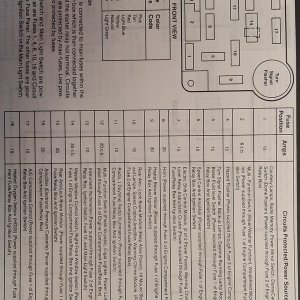
I think that you're on the right track, as far as wiring the load (i.e., the lights; make sure the switch rating will handle them). This part would the 3 terminals, wired as in your drawing.*
What I'm thinking is that 2 LED lights in the switch are not bussed internally; but rather they're externally wired which accounts for the other 4 terminals.
You can try wiring it like in your diagram, and if the switch works, but doesn't light up, then you're looking at the 4 terminals needing to be wired for the LED lights. Hopefully, the LEDs already have resistors on them inside the switch. Otherwise, they'll need 5 volts instead of 12 volts.
Have you tried Googling "Contra switch" to see if you can find instructions for it? Good luck.
* Edit: there could be more than one possible wiring configuration, depending on the switch design. For example, the center pin could be common to the outer pins, depending on the switch position. In this case you'd have one power in, and only one power out to turn the lights on and off.