Welcome to TRS
")
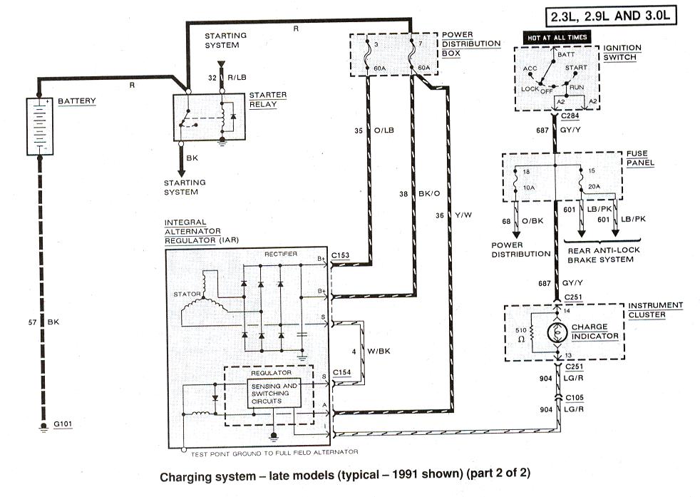
If alternator has internal voltage regulator it should only have a 3 wire connector for voltage regulator
Yes, Yellow wire is connected to battery via fusible link, so should have 12volts all the time, this wire monitors battery/system voltage for voltage regulator
There should be a Light Green wire as well, this is the ON/OFF switch for alternator, it comes from Battery Light in the cab, it often has a separate fuse in cab fuse box.
When you turn on the key Battery Light should come on, if not then fuse is blown or light Green wire is disconnected at alternator or somewhere between there and the dash.
Light green wire should have 12v key on, 0 volts key off
Battery Light bulb has a resistor bypass so system can still charge if bulb should burn out.
An alternator will drain the battery if left ON when engine is off, green wire provides Startup Voltage to get alternator working, and also shuts of voltage when its power is cut, preventing alternator from draining battery.
If alternator's normal 13.5 to 14.5 output volts should stop then Battery Light would come on like it should do with key ON engine off, before starting engine.
So it serves a dual purpose, on/off switch for alternator and no-charge warning if engine is running
White wire is a jumper to Stator on alternators case
Then there will be 1 or 2 larger wire(s) connected on the Stud terminal, B+ terminal, wires can be Orange or even Black with a stripe.
These run to battery via fusible links so should also have 12v all the time, no volts on these wires means fusible links are burned out, so no alternator voltage would reach the battery
In 1989 the yellow and B+ wires should run to Starter Relay(solenoid) post with Battery Positive cable on it, and thats where the fusible link ends are.
The Fuse box connections may or may not be used in 1989 for these wires
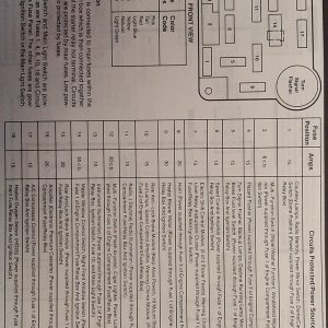
Diagram here:
http://www.therangerstation.com/tech_library/EDiagrams/files/Diagram_charging_1991_2.JPG
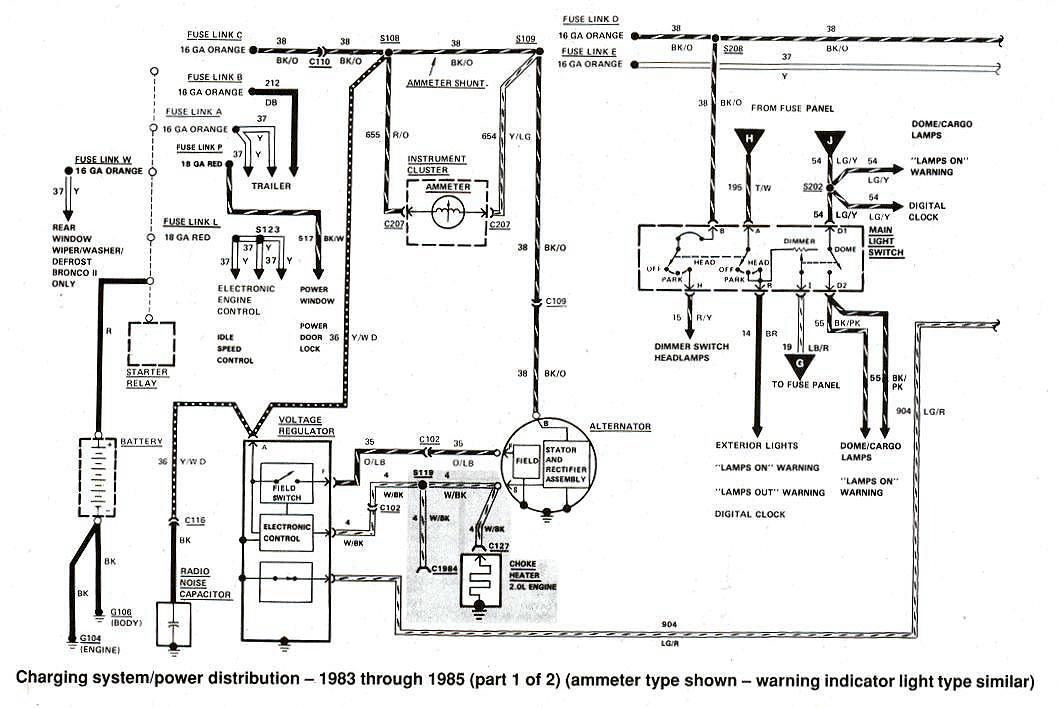
External voltage regulator wiring here:
http://www.therangerstation.com/tech_library/EDiagrams/files/diagram_charging_1983to1985_1.JPG
It did use 4 wires to regulator
And some did converter the 1G external regulator alternators to the 2G or 3G internal regulator alternators when 1G quit working.
So you could have a conversion which would make the wiring different, i.e. splices
The blower motor would have 12v key on so maybe somebody used that for the GREEN wire, and it should work but would need to be on the 12v side of the blower motor, not the resistor side which is the GROUND side, the ground side would have 12v when cab switch for fan was off, but 0v when fan switch was in any other position but OFF


