Disclaimer
Activities and vehicle modifications appearing or described at The Ranger Station and its pages may be potentially dangerous. We do not endorse any such activity for others or recommend it to any particular person – we simply describe the experiences and opinions of other Ranger/Bronco II owners. If you choose to engage in these activities, it is by your own free will and at your own risk. Any and all modifications will likely cause a vehicle to behave differently than stock. Some modifications may significantly increase your risk when driving the vehicle or be dangerous in some driving situations. Use good judgment when engaging in any activity or making any modifications. Do not take unwise risks. Consult a certified professional if you are not sure of something. The Ranger Station and the authors of these articles assume no liability for how any particular individual chooses to use the information presented here. Some of these modifications may void your vehicles warranty.
Introduction
One of the best improvements you can make to a Ford TTB (Twin Traction Beam) suspension is to replace the stock radius arms with extended (longer) radius arms to increase suspension / wheel travel. Some people buy extended radius arms from suspension companies, and some have built their own. For those of you interested in making your own, here’s some information that should help.
The Most Common Method of Building Longer Arms
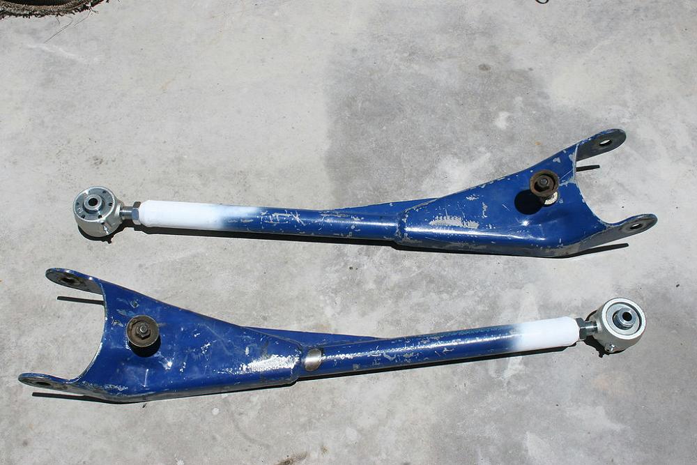
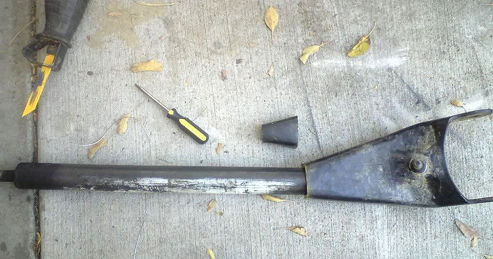
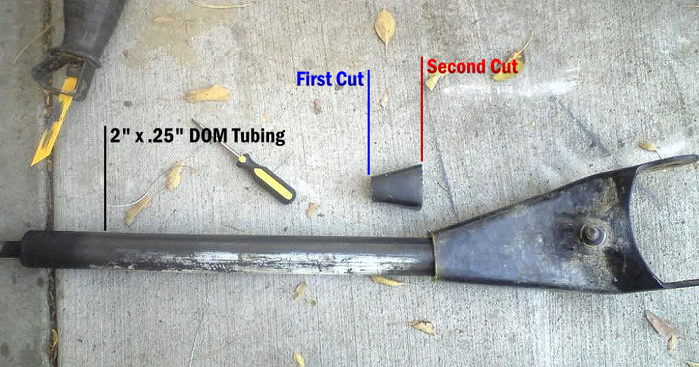
The most common method of building your own extended radius arms is to start with the stock radius arm and cut off the threaded end in the area marked ‘First Cut’ in the photo below. Your extension will be either a section of 2.0″ x 0.25″ wall square or round tubing. Believe it or not, I see more people make these with square tubing than round.
The first step is cutting off end where it’s marked ‘First Cut’ in the image below. Then cut off enough area too allow the tubing to fit into the radius arm (Second Cut).
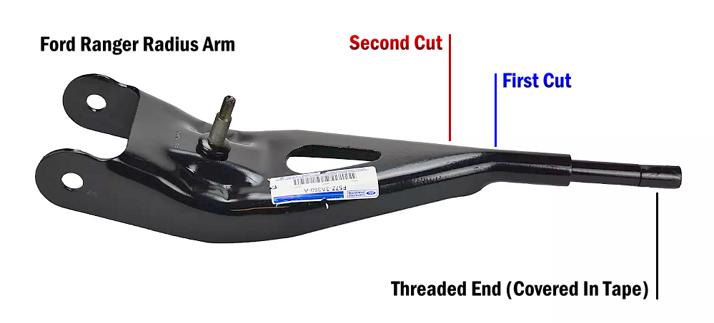
Below you can see where the end of the radius arm was cut off.
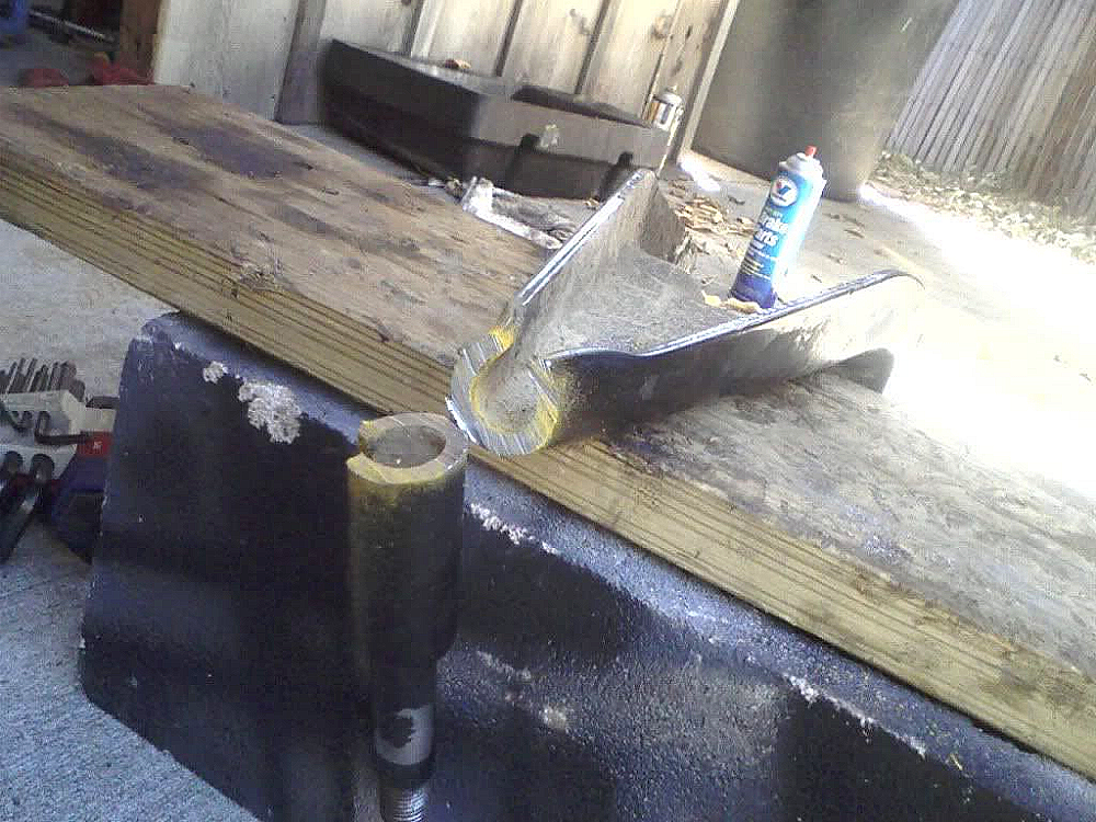
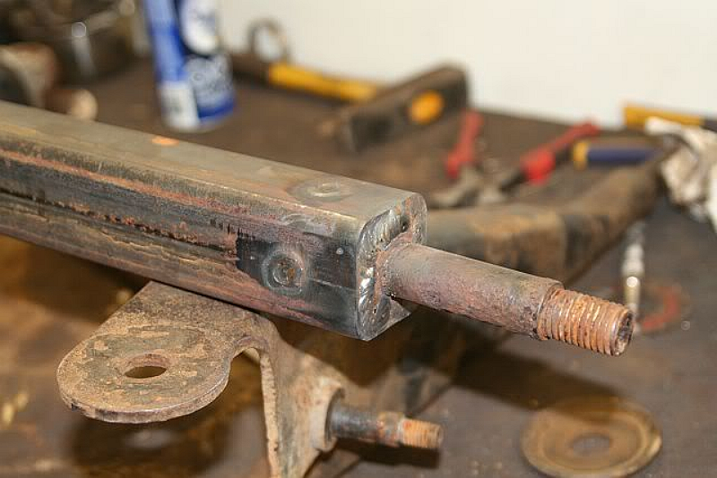
This treaded end will be inserted into the end of your new section of tubing that you’re adding. Below you can see where the second piece was cut off to allow the 2.0″ x 0.25″ tubing to be inserted into the radius arm.
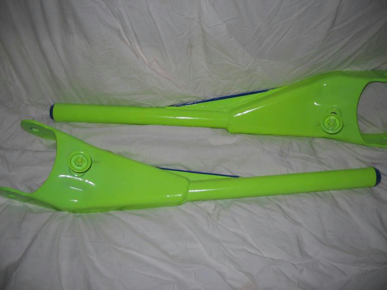
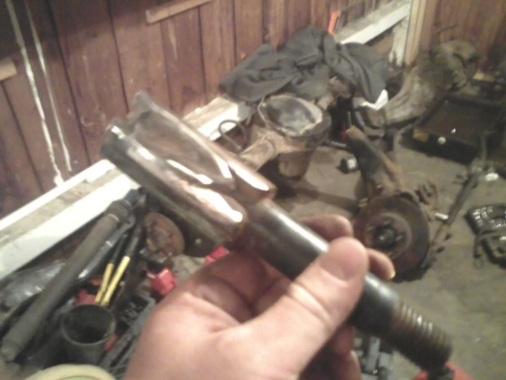
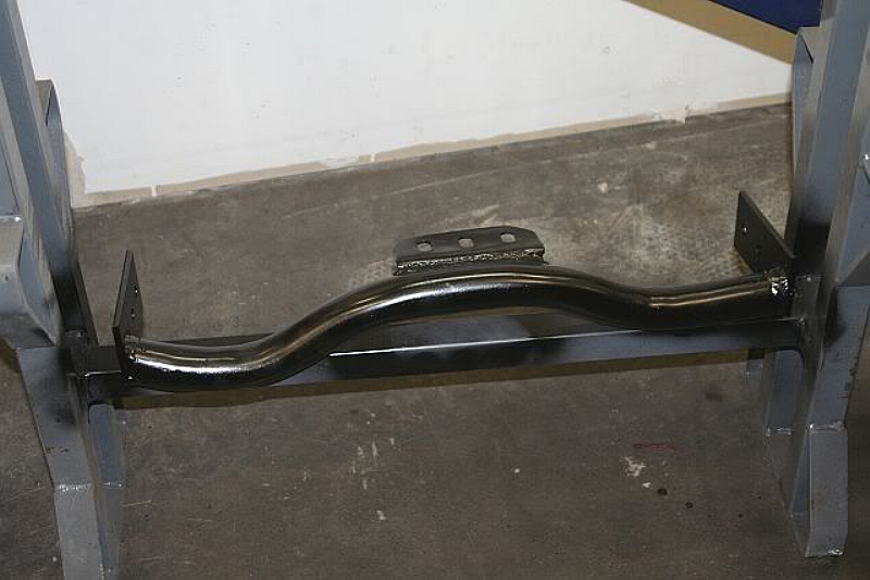
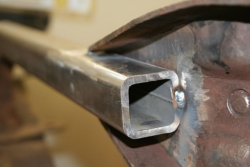
Here’s a 2.0″ x 0.25″ section of square tubing tack welded into place.
The end section that you cut off gets inserted and welded into the end of your new extension.
How Much Longer Should The Radius Arms Be?
Typically, you lengthen them 12-inches if you want to keep your radius arm mounts and transmission cross member separate, and 15-inches if you want to incorporate the mounts into a new transmission cross member.
Setting The Caster
What Is Caster
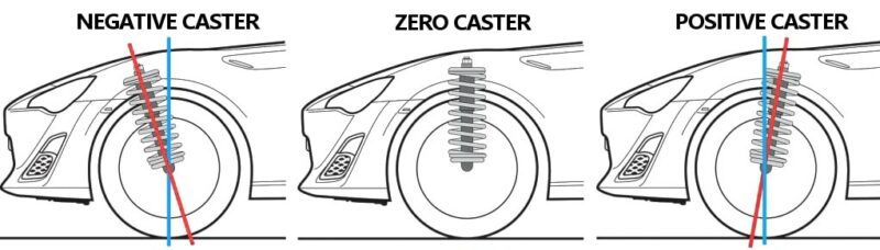
Caster angle refers to the location of your vehicle’s upper ball joint compared to the lower ball joint. If your upper ball joint or strut mount is located more toward your vehicle’s rear than the lower ball joint, your vehicle has a positive caster. Positive Caster provides better straight-line tracking which means you won’t have to turn the wheel as often to correct for divots and bumps in the road. Positive caster improves your vehicle’s responsiveness when rounding corners and improves your vehicle’s stability when traveling at higher speeds.
As you may have guessed, negative caster is the exact opposite of positive caster. When the upper ball joint is more towards the vehicle’s front than the lower ball joint, the vehicle has a negative caster which causes reduced stability and poor handling.
How To Factor It into Your Radius Arm
The Ford Ranger TTB front axle is designed with 5 degrees of positive caster.
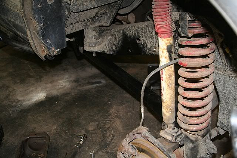
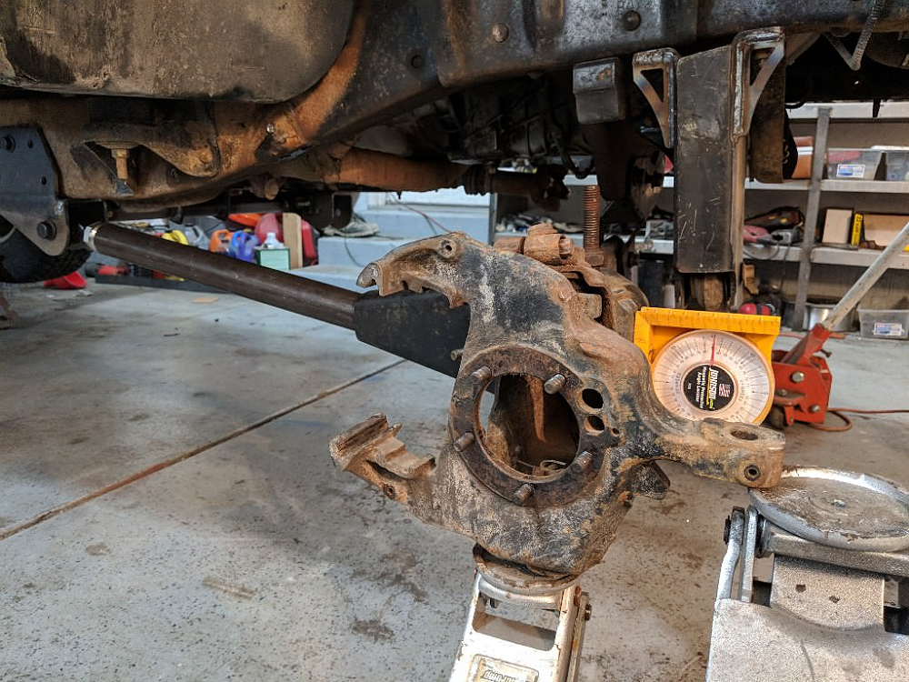
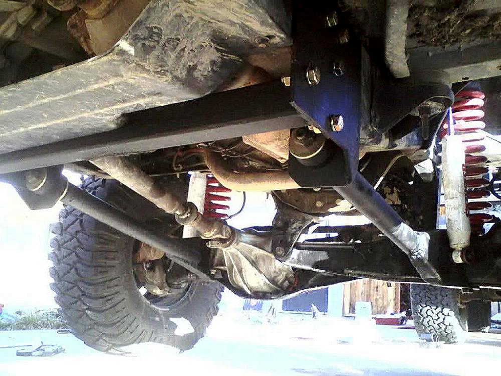
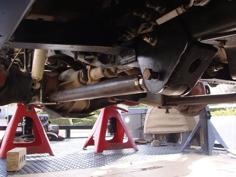
First, you’ll need to know where your rear radius arm mounts are going to be (See Radius Arm Mounts further down this page). Then you’ll need to position the axle beam so that it will have the right amount of caster.
With your front springs removed, position the axle beams so that it’s sitting at what would be the suspension’s optimum ride height (beam pivots 1-inch above the wheel hub centerline) and then square the beams to the ground (face of the beam is 90 degrees to the ground, and the bottom of the beam is parallel to the ground). This should give you approximately 4-5 degrees of positive caster at your ball joints. Any minute corrections from there can be done with the camber/caster bushings.
With the beams in place, you can position your new tubing extension between the radius arm and the rear mount and then tack weld it into place.
Welding The Radius Arms
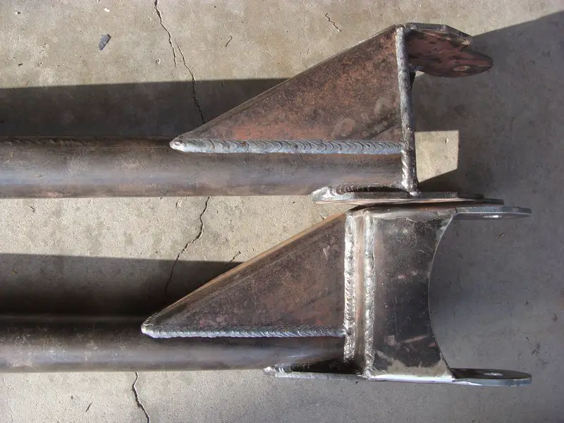
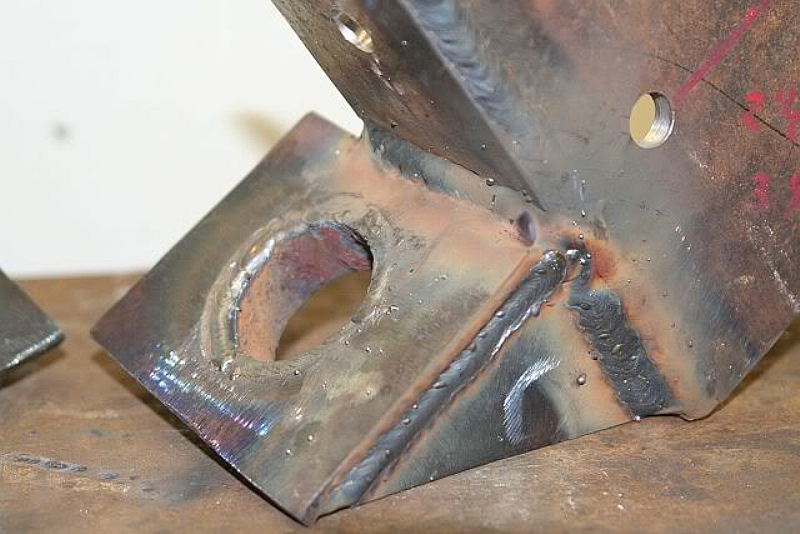
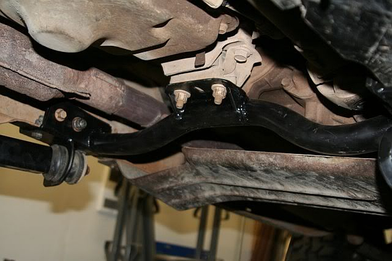
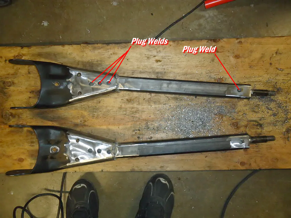
With your caster set and your radius arms tack welded into place, it’s time to weld them up. When you weld the extension to your radius arm you want to make sure you add plug welds. You don’t want to just weld around the edges. Plug welds will help add more strength and create a better bond between the radius arm and the new extension. In the photo below you can see that the radius arm is plug welded to the new section of tubing, and the original section that was cut off and inserted into the end if the new tubing has been plug welded as well.
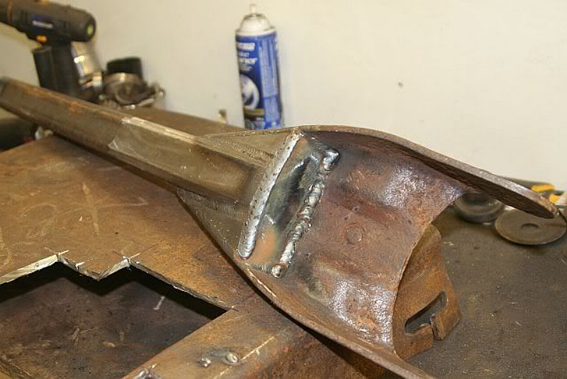
You should also box in the back side of the arm with 1/4-inch steel plate to add strength and brace the area where the two pieces were welded together.
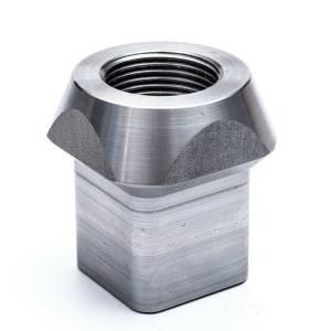
Johnny Joints
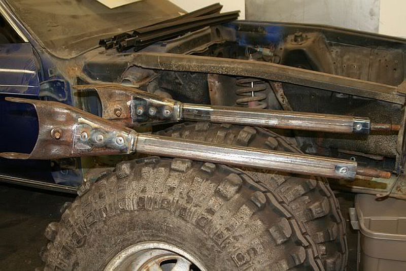
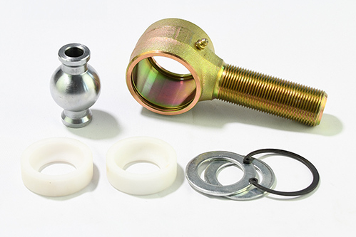
You may decide that you want to use Johnny Joints instead of the threaded post and bayonet-style bushings that were originally on the radius arm. A Johnny Joint is a rebuildable flex Joint that consists of a metal threaded housing, washer, bushing, ball assembly and snap ring. The housing has a snap ring groove and a hole for a grease zerk.
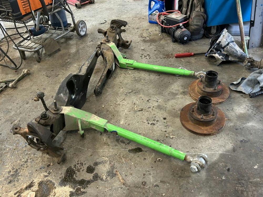
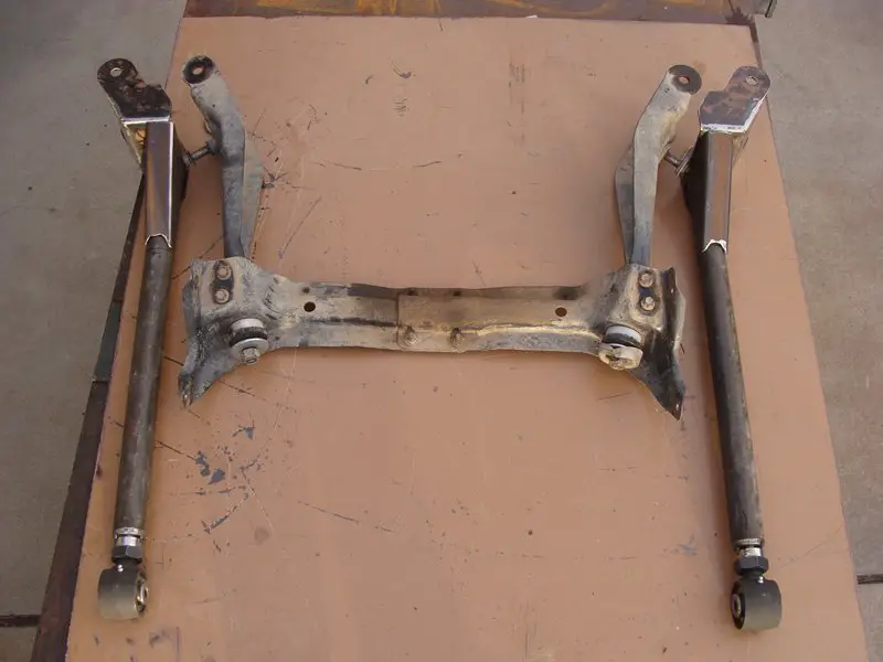
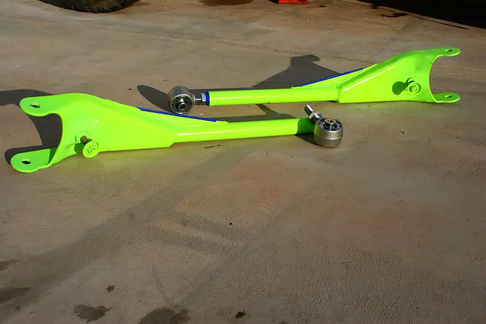
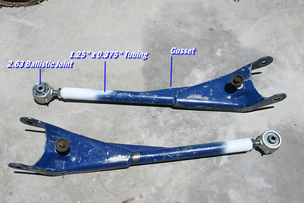
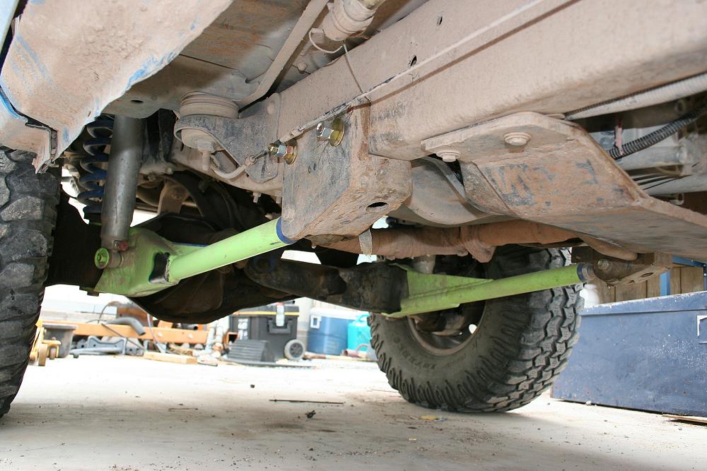
The radius arms below were built using 1.25″ x 0.375″ DOM tubing and 2.63 Ballistic Joints on the end. Note the extra gusset added for even more strength. Ballistic is no longer in business, so a Johnny Joint would be the next closest thing.
If you want to use a joint on the end of your radius arm, you’ll need a tube adapter that you cab weld into the end of your tube and then screw the joint into. You should be able to find threaded adapters for both round and square tubing.
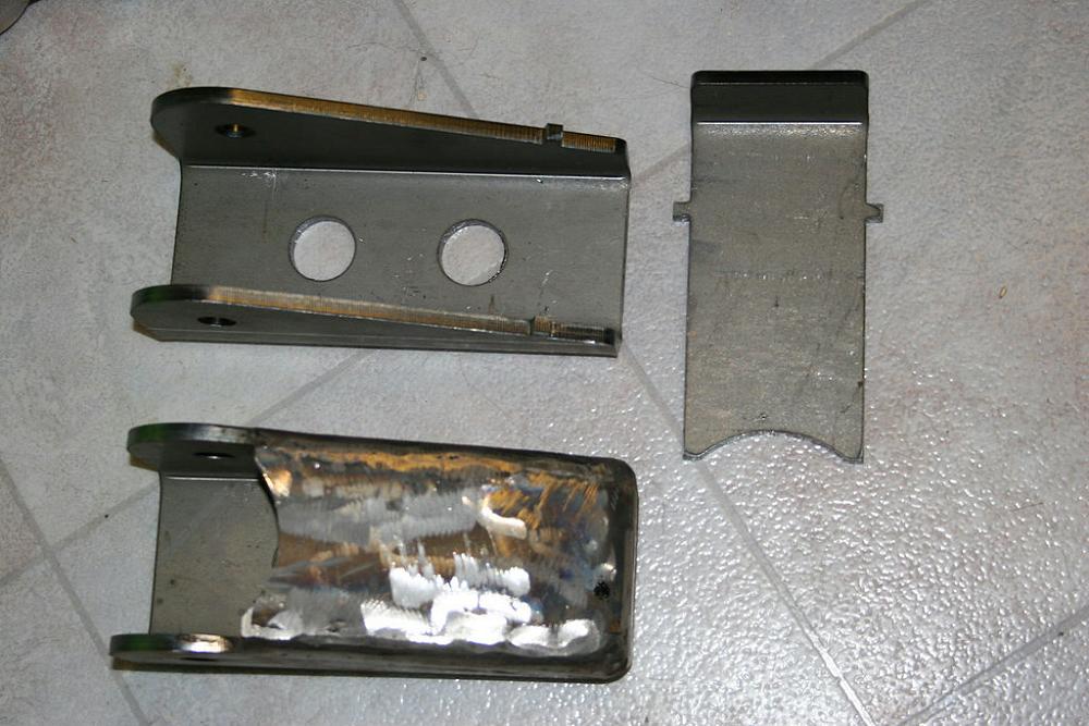
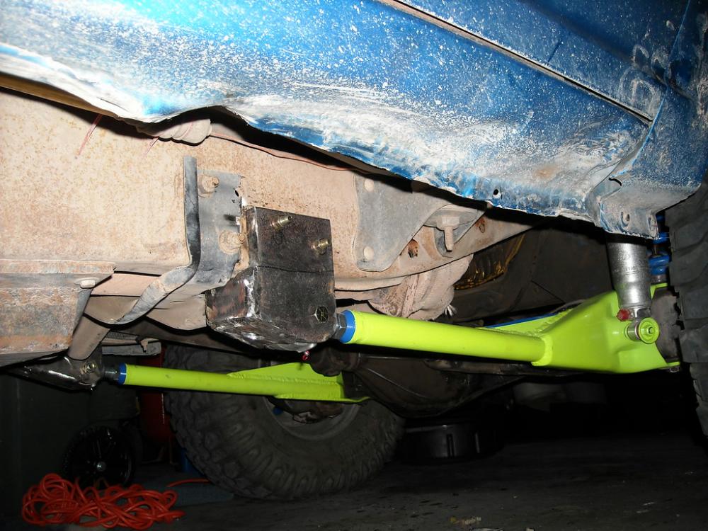
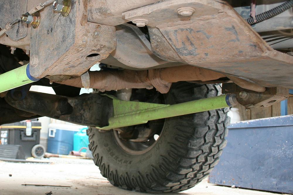
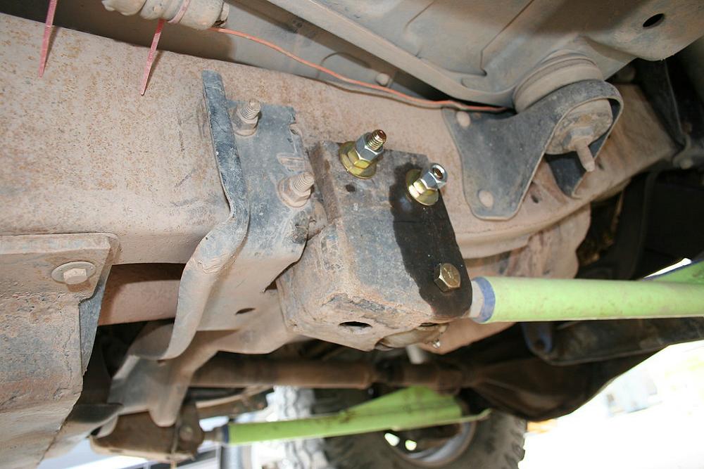
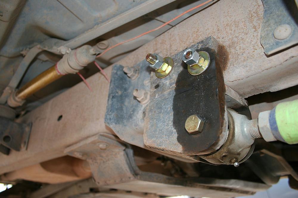
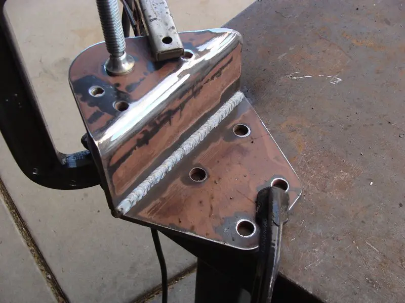
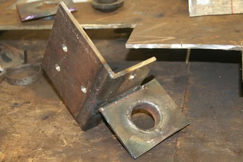
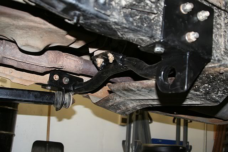
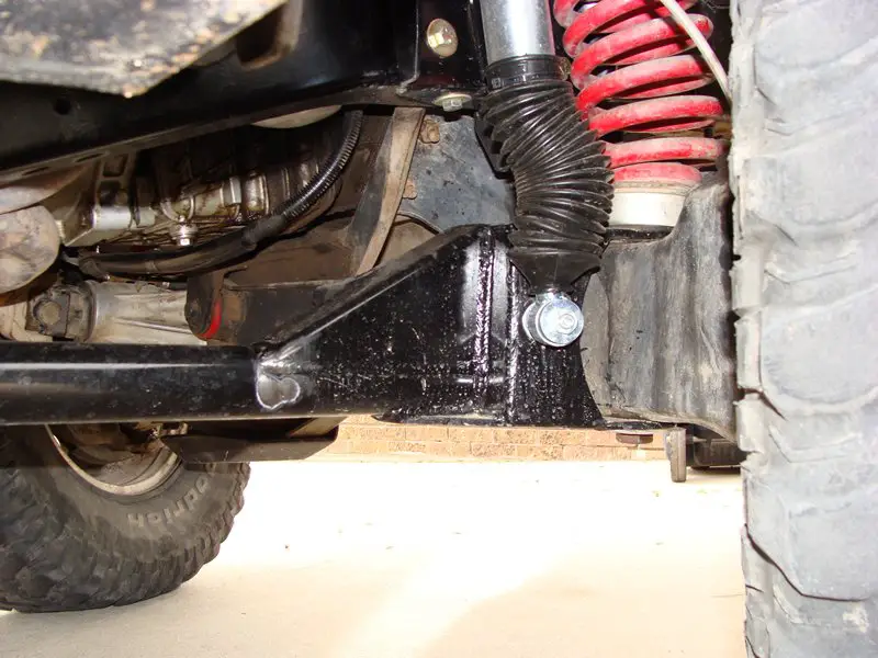
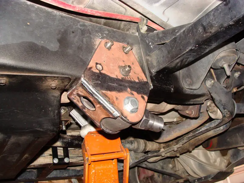
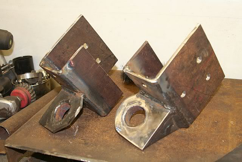
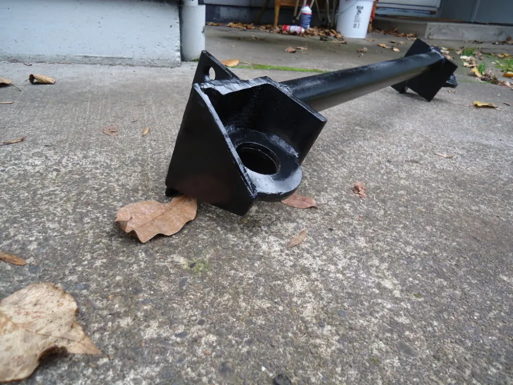
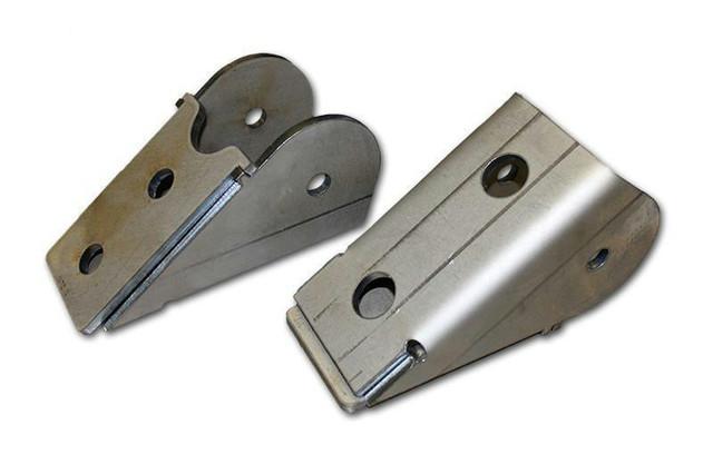
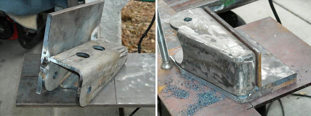
Radius Arm Mounts
You’ve made your extended radius arms and now you’re going to need a mount for them. Hopefully you already made them because you needed to know where the radius arm was going to mount when you set your caster. If not, raising and lowering the mounting location will increase or decrease caster.
Most people just make their own mounting brackets out of 1/4″ steel plate.
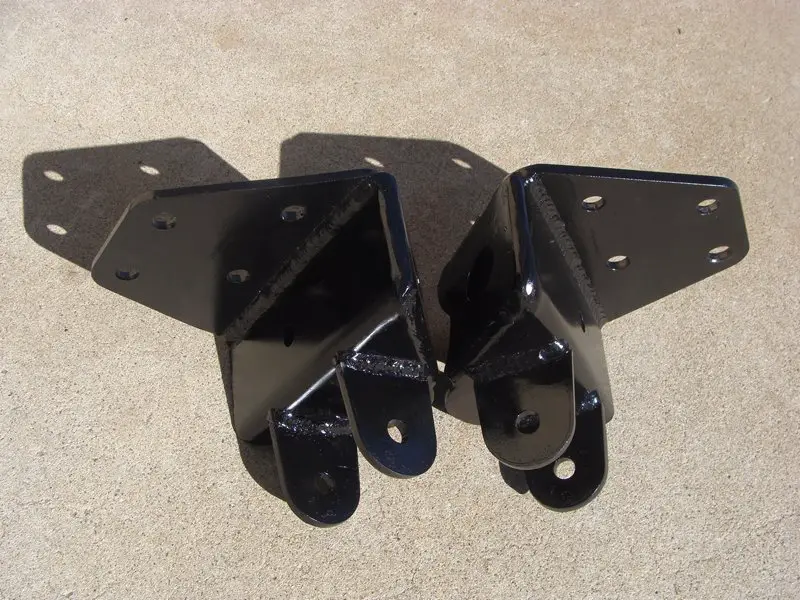
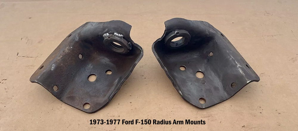
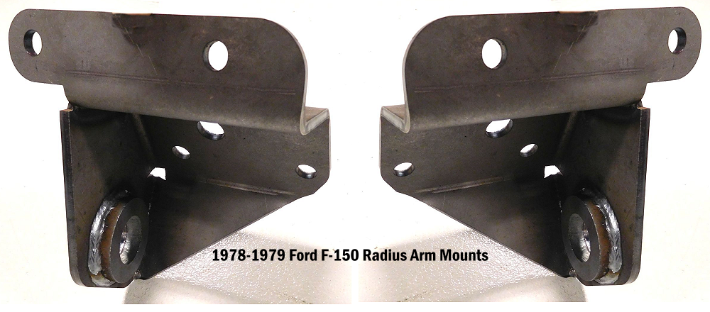
You may even be able to use a set of radius arm brackets from a Ford F-150. 1973-1977 F-150 mounts put the radius arm up closer to the frame than the 1978-1979 mounts do.
If you’re using a Johnny Joint, then you obviously need a completely different type of mount.

Good Luck!
Good luck on your build. If you decide to make a set of extended radius arms, please be sure to post photos in our forum.
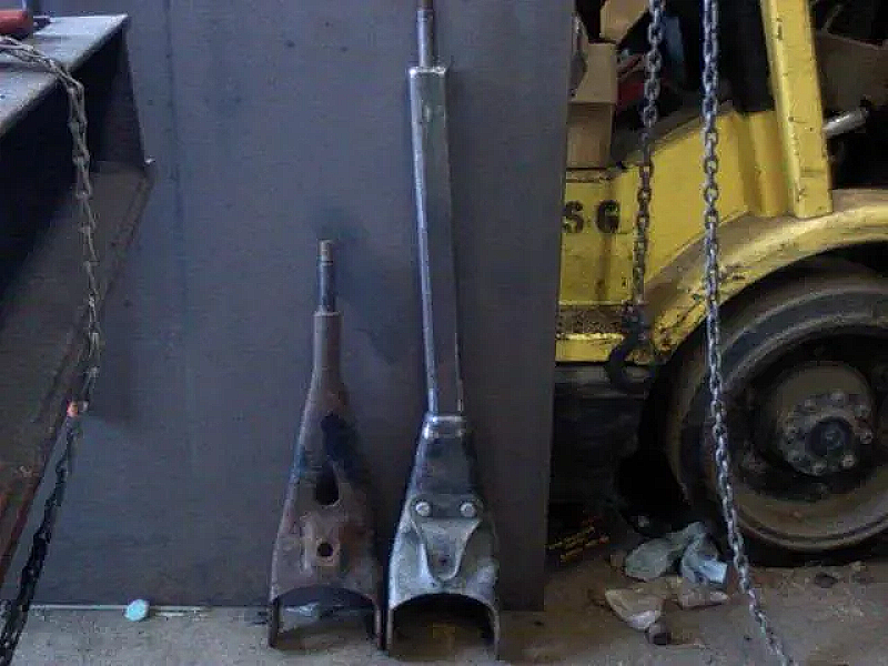
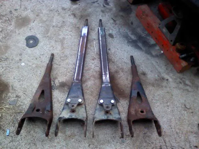
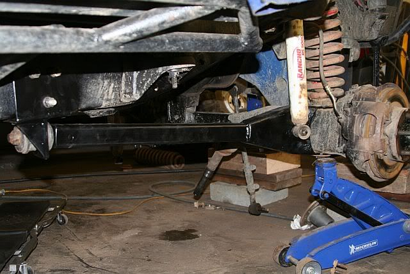
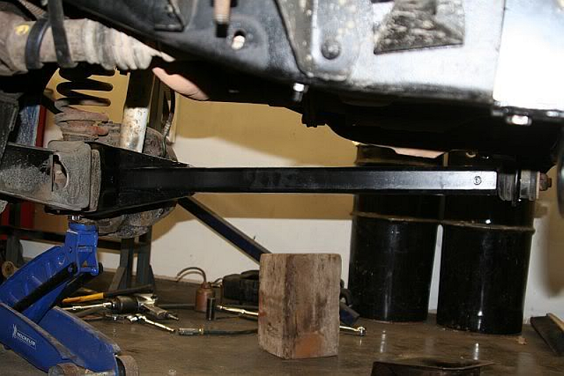
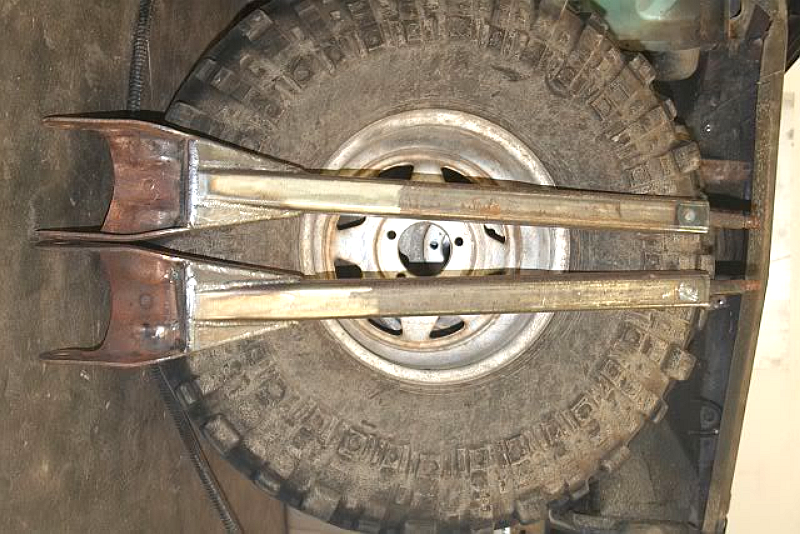
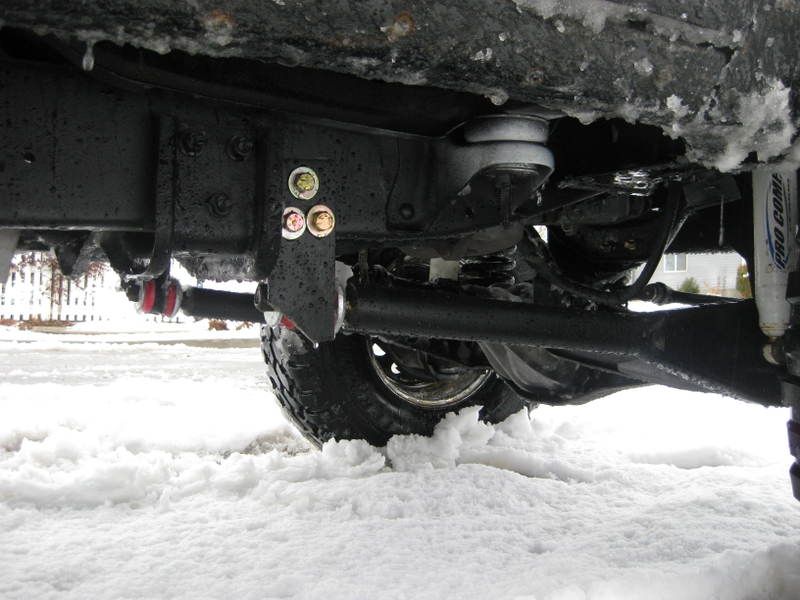
A Few More Photos