Another of Ford’s “better ideas” is the electric shift motor on the transfer case. Evidently someone thought that two shift levers sticking out of the floor was one too many, and that it would be so much more convenient to just push a button and shift on the fly. I’ll leave that discussion for another venue. What I want to show you here is what’s inside that motor and what you can do in the way of servicing it to make it run more reliably.
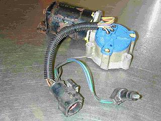
This is a used shift motor I got from a wrecking yard. Before I put it on my own truck, I wanted to see what it looked like and see if I could keep from replacing a problem motor with a problem motor. I’m by nature a curious type (occupational hazard of being an engineer, I guess.) So I opened it up and found the maintenance points. The cut green wire is a ground. I guess the guy who harvested this part didn’t have the right tool. As long as the main plug is intact, it’s not a problem. When you get one from a wrecking yard like this, be sure to also get the magnetic sensor as part of it. This detects where the internal transfer case parts are so the control module knows what range you are in. Clean the main wiring plug with contact cleaner and use a dab of dielectric grease on each terminal before you install it. Also be sure that any wire splices you make (like the ground wire here) are sealed tight against anything that might get into the joint when you are doing some hard four-wheeling. Doesn’t take much crud here to upset things and make it quit working. If you don’t mind a long drive home in low range, it’s no problem!
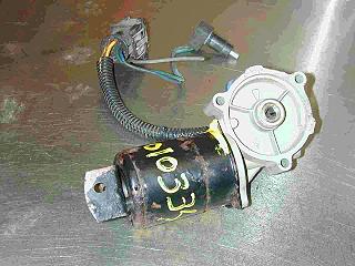
The other side of the motor assembly shows the drive gear that mates to the shift shaft in the t-case. In both pictures you can see the yellow paint on the screws. The wrecking yard put this on to detect if I opened it and tried to return it after robbing parts. As I don’t intend to return this motor, I ignored it. You should make note of the alignment of the triangular opening in the center shaft so you can get it back together in the same orientation. It’ll save you some trouble when you put it back together.
I scribed a mark for the alignment of the blue cover to make sure I got it back on right, too.
After you break off the anti-tamper pins in the center of the Torx screws on the blue cover, this is what you will find inside this end of the assembly. About the only thing you can do here is to put some fresh lithium grease on the gear. There is a half-circle hole in the end of the gear shaft that aligns with the stub sticking out of the blue cover. Inside the blue cover is a disk that rotates and sends alignment signals back to the control box. (That’s what all the wires sticking out of the blue cover in the top picture are for.) You will have to make sure the triangular hole in the other end of the gear shaft is in the correct alignment when you put it back together, then get the half-round stub to align with the other end, then get the blue cover lined up with the body marks. Then it’s time to go the other end, where the real action is. You could probably get away with not opening this end if you wanted to skip it.
Three Phillips screws later, the motor comes apart. The permanent magnets in the housing are strong, so you will have to persuade the rotor to come out. Note the black band of carbon dust around the brass rotor poles. This is one problem that can keep the motor from working properly.
A bit of contact cleaner on a paper towel gave me this after I wiped the rotor and brushes. That’s all it takes. Now that it’s clean, it’s time to put a dab of lithium grease on the end of the rotor shaft and the worm gear, then re-assemble the motor. But there’s still one trick left before you get that step done.
The brushes will frustrate you to no end if you don’t know this trick. They might even tempt you to use strong language! If you push the brush in all the way, then put the wire in the notch, you can put the motor together with no problem at all. (Compare this picture to the way the brushes are hanging loose in the first picture of the inside of the motor.) Just before you close the motor housing the last fraction of an inch, but after the rotor contact area is in as far as the brushes, reach a real small screwdriver blade, paper clip, or some other tool in between the housing and the brush plate and free the wire. You will hear the brush snap into position ready for duty. Make sure you do both sides, as there is nothing to cause them to pop out on their own.
That’s all there is to it! Close the motor, put the three screws back in, make sure everything is snug, and you’re ready to install it on the transfer case.


