
If you have been reading or listening to any discussions about the Ford Twin Traction Beam (TTB) suspension, you may have heard that you have to factor in 1.5× for the leverage created by the axle beam when calculating or considering a spring rate. What is this Leverage Factor?
Simplified Explanation:
With the Ford TTB suspension, Leverage Factor refers to how much a given force (such as the vertical load from the vehicle’s weight) is multiplied as it is transferred through the suspension components. It’s a function of the relative lengths and pivot points of the components involved — in this case, the axle beam, the radius arm, and the pivoting axis.
Components:
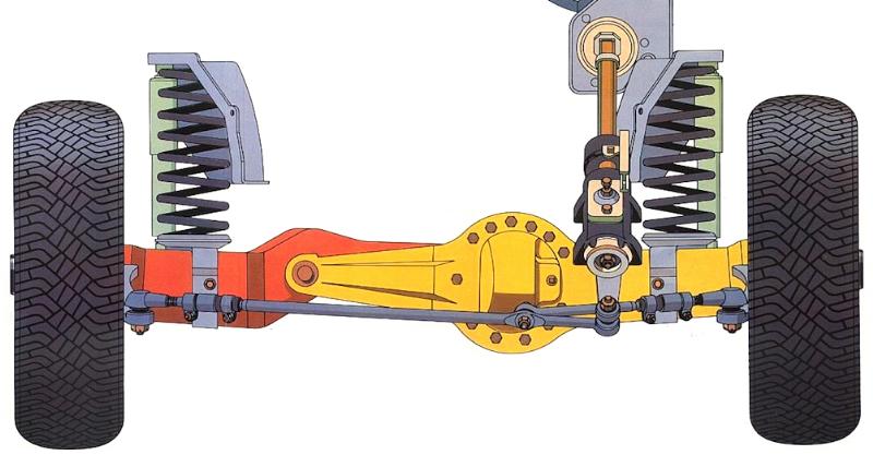
1. Axle Beam: This is the main part of each side of the axle to which the wheel is attached to and is connected at the opposite end to a pivot on the chassis. It moves up and down in response to the terrain or road surface.
2. Radius Arm: The radius arm locates the axle beam fore/aft and is also connected to a pivot on the chassis. It too moves up and down in response to the terrain or road surface.
3. Leverage in Suspension: In this system, the Leverage Factor is determined by the lengths of the axle beam and radius arm, and where along their length the coil spring acts upon them. When weight of the vehicle acts upon the wheel, this force is multiplied by the Leverage Factor at the coil spring.
4. Motion Ratio: This is how much the coil spring (also the shock) moves relative to the wheel. Because the spring & shock are located at a mid-point between the wheel and the TTB pivot axis, their movement will be less than that of the wheel. Consequently, the shock will need to have a stiffer valve rate to provide the same amount of damping as a shock mounted directly at the wheel.
Leverage Factor in Action:
Imagine you have a wheelbarrow. If you apply a force at the end of the wheelbarrow (by lifting the handles), the force at the load (wheelbarrow tub) will be much greater, allowing you to lift a load that is much heavier than you otherwise would be able to (this is Leverage Factor). The tradeoff is that the amount the load is lifted is less high than the handles are lifted (this is Motion Ratio). The wheel itself acts as the fulcrum.
Similarly, in the TTB suspension, the leverage factor works by taking the force applied at the wheel and multiplying it by the Leverage Factor of the system — how long the radius arm and axle beam are, and where the spring is placed relative to the pivots. The result is that the spring will experience a higher force than what is directly applied at the wheel.
Calculating Leverage:
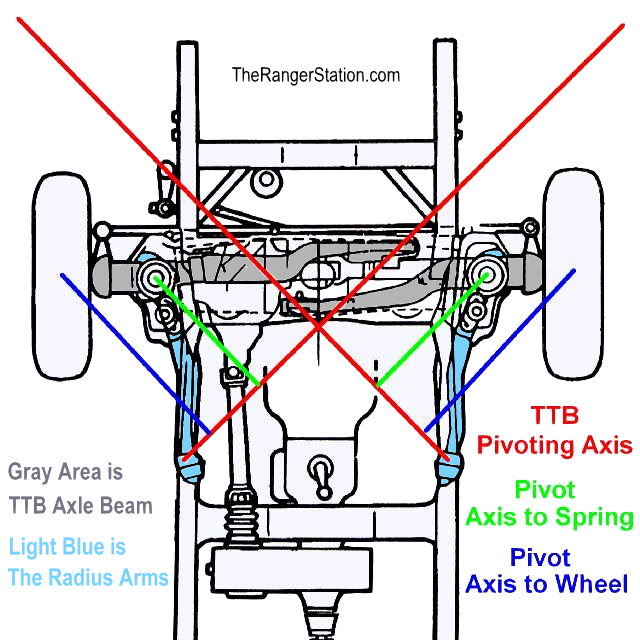
In the diagram above you will see that there is a Pivoting Axis. The Pivoting Axis is a straight line drawn through the axle beam mounting point at the frame (crossmember) and where the radius arm mounts to the frame. You will need to take two measurements:
1. The distance from the center of the tire’s contact patch to the Pivoting Axis (D1).
2. The distance from the center of the coil spring mount to the Pivoting Axis (D2).
(a plumb-bob & piece of chalk will make this easier by allowing you to mark these points on the ground where you can then use a tape measure)
To determine the Leverage Ratio, you will divide the distance from the center of the tire to the Pivoting Axis (D1) by the distance from the center of the coil spring mount to the Pivoting Axis (D2).
Example:
For the Ranger TTB suspension with stock Radius Arms:
D1 = 25.25-inches
D2 = 17.125-inches
LF = Leverage Factor
Leverage Factor = D1 ÷ D2
25.25 ÷ 17.125 = 1.474 (Leverage Factor)
In this example, the suspension has a leverage factor of 1.474:1 meaning that the suspension is applying 1.474 times the force (weight of the vehicle) onto the coil springs.
Measuring The Weight:
The weight used in your suspension calculation is going to be the sprung weight of the vehicle multiplied by the Leverage Factor. The sprung weight is the weight that sits above the springs, or more simply, the weight of the front of the vehicle minus the weight of the axle, tires, and wheels.
Example:
Let’s say the front of your truck weighs 2400 lbs.
The axle, wheels, and (stock-size) tires roughly total 300 lbs (unsprung weight).
Sprung Weight = Weight – Unsprung Weight
2400 lbs – 300 lbs = 2100 lbs
The sprung weight in this example would be 2100 lbs (2400 lbs – 300 lbs). Now we need to multiply it by the Leverage Factor and then divide it in half to get the amount of force (weight) being applied to each of the front springs:
2100 lbs x 1.474 (Leverage Factor) ÷ 2 (each front spring) = 1547.7 lbs applied to each spring
2100 lbs x 1.474 (Leverage Factor) = 3095.4 lbs.
3095.4 lbs ÷ 2 = 1547.7 lbs of force (weight) at each of the front springs.
Calculating Compressed Spring Height:
Spring Rate is a measurement of how far a spring compresses per unit of force. A coil spring with a 430 lb/in rating will compress 1-inch for every 430 lbs applied to it. If we take the amount of force (1547.7 lbs) and divide it by the spring rate (430 lb/in), we get a measurement of how far the spring will compress.
Example:
Force (weight) on spring = 1547.7 lbs
Spring Rate = 430 lb/in
Amount Spring is Compressed = Force (Weight) ÷ Spring Rate
1547.7 lbs ÷ 430 lb/in = 3.6 inches
If this spring has a free height (no weight on it) of 20-inches, then it’s compressed height (with weight on it) would be 16.4 inches:
Compressed Spring Height = Free Height – Amount Spring is Compressed
20-inches – 3.6-inches = 16.4-inches.
Having this information allows you to calculate what your ride height is going to be. The compressed height of a stock 1983-1997 Ford Ranger coil spring is 10.50 inches. 16.4 – 10.50 = 5.9 inches. So, in this example, the coil spring would provide 5.9 inches of lift.
Why The Leverage Factor Matters:
If you’re trying to calculate how much a coil spring will compress, you’ll need to know the spring rate of the coil and the weight (force) being applied to it. In order to calculate the correct amount of weight, you’ll need to multiply the Leverage Factor into it.
In the event you don’t include the Leverage Factor and simply use the weight on the wheel (2100 ÷ 2 = 1050), you would end up with a much different result:
1050 ÷ 430 = 2.44 inches (amount the spring is compressed)
3.6 – 2.44 = a difference of 1.16 inches
As you can see, that is pretty significant. So, you can see how important it is to include the Leverage Factor in your calculations.
Conclusion:
In your TTB suspension, the Leverage Factor helps explain how forces are transferred and magnified between the axle and the vehicle’s frame. By understanding the lengths of the axle beam and radius arm, as well as their pivot points, you can predict how different parts of the suspension will respond to various forces, like bumps or the vehicle’s weight.
NOTE: You may also be interested in How To Calculate Motion Ratio & Wheel Rate For A Ford TTB Suspension