|
|
|
|
Ford C5 Automatic Transmission Diagnosis |
|
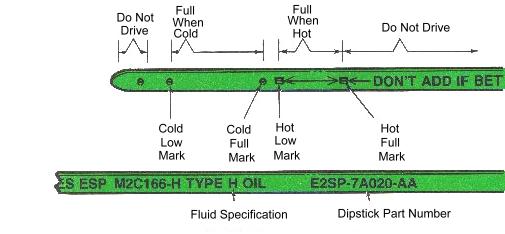
Fluid level should ideally be checked with the transmission at operating temperatures. Test conditions are: 1) Engine at hot curb idle. 2) Shift selector in Park (after moving through all the ranges to Fill clutch and servo cavities). For road testing, a cold check can be made. The fluid level be between the inner holes (Figure 57). If the level is at or below the lowest hole, the vehicle should not be driven without adding fluid. If it's overfilled, the vehicle should not be driven without removing fluid.
HOT FILL
The final fluid rill should always be between the arrows (Figure 57), at operating temperature. IMPORTANT: DO NOT OVERFILL. THE SPACE BETWEEN THE ARROWS IS LESS THAN ONE PINT. DO NOT FILL TO THE ARROWS UNLESS THE TRANSMISSION IS HOT.
CHECK FOR LEAKS If the fluid level checks low, be sure to leak test the transmission after the road test. Locate and repair leaks. FLUID SPECIFICATION Use only Type H fluid as specified on the dipstick. Use of any other fluid can cause damage and will void the warranty CHECK FLUID CONDITION, TOO The fluid should be clean and normally not discolored. Fluid used with the C5 automatic transmission contains a detergent which retains in suspension particles generated during normal transmission use. This characteristic may result in a dark coloration of the fluid and does not by itself indicate malfunction or need for repair. SMELL THE FLUID A burnt smell or rotten egg odor indicates a major failure. Overhaul is required. LOOK FOR THESE CONDITIONS...
* Burnt - burnt clutch or band. Overhaul transmission replace converter, flush cooler lines * Solid residue - clutch or band material. Overhaul transmission, replace converter, flush cooler lines.
BEFORE ROAD TEST
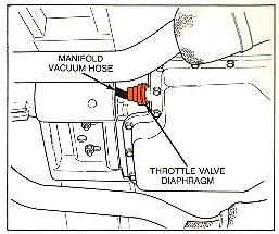
If these symptoms show up on the road test, check out the vacuum system and leak test the diaphragm. MANIFOLD VACUUM CHECK
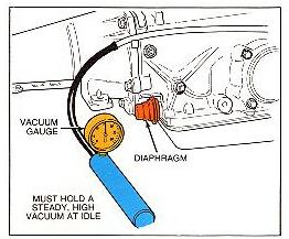
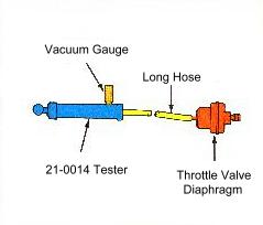
1. Remove the vacuum hose and connect it to a vacuum gauge. 2. Run the engine at hot curb idle. Check for a steady idle vacuum. 3. "Goose" the engine and let it return to idle. The vacuum should drop; then return to a steady high vacuum. If there is not manifold vacuum to the diaphragm, inspect the hoses and check for proper routing with the vacuum schematic.
DIAPHRAGM INSPECTION
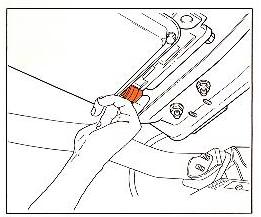
Check at the vacuum port of the diaphragm for transmission fluid or water (Figure 60). · Transmission fluid means the diaphragm is a leaker. Replace it. · Water may have leaked in through the vacuum system, causing the diaphragm to rust or freeze during cold weather, and stick. This also would cause shift problems, and a new diaphragm will fix the condition.
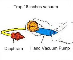
The leak test is simple, and can be done on or off the vehicle. 1. Remove the manifold vacuum hose and connect a vacuum source to the diaphragm. 2. Apply 18 inches of vacuum (Figure 61) to the diaphragm and see if it holds. The diaphragm is probably OK if it will hold vacuum. Replace it if it fails to hold vacuum, or if the rod doesn't move with vacuum changes.
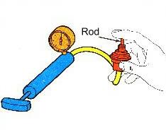
* Insert the throttle valve operating rod (Figure 62) and push it back and forth. If the diaphragm binds, install a new one. * Install a new rod if the rod is bent. THROTTLE VALVE INSPECTION
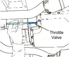
1. Check the throttle valve for free operation in its bore in the case (Figure 63). 2. If the valve sticks, remove it from the bore and inspect it for burrs. A sticking throttle valve can often be deburred by rolling it on a flat Arkansas Stone . . . and quickly correct a shifting problem. THROTTLE VALVE INSPECTION Do this before you install the diaphragm: 1. Check the throttle valve for free operation in its bore in the case (Figure 63) 2. If the valves stick, remove it from the bore and inspect it for burrs. A sticking throttle valve can often be deburred by rolling it on a flat Arkansa Stone...and quickly correct a shifting problem.
Manual Linkage BEFORE ROAD TEST
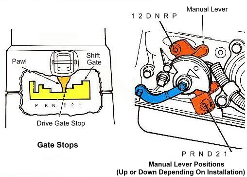
1. Pull shift lever toward you (or depress thumb button for floor shift) to "ungate" it. Move it through all the ranges. 2. Feel the detents in the transmission. Are they synchronized with the markings on the shift selector? 3. Shift to D and let the lever drop into position. 4. Check if the shift gate pawl is against the D stop by trying to move the lever toward 2 without "ungating" it, (Figure 64). If there is free movement to the D stop, or if the pawl is up on the 2 stop, an adjustment is required. DO NOT DRIVE THE VEHICLE IF THE ADJUSTMENT IS NOT CORRECT.
LINKAGE ADJUSTMENT 1. Locate the slotted rod in the linkage. It will usually be at the transmission manual lever, but may be elsewhere. (Refer to the Shop Manual if necessary.) Loosen the nut or screw. 2. Put the selector in D firmly against the gate stop. 3. Shift the manual lever on the transmission (Figure 64) to the D position. It will be three detents away from Park. 4. Tighten the nut securely. 5. Repeat the linkage check with the shift lever and gate stops before driving the vehicle.
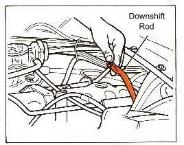
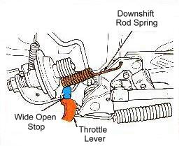
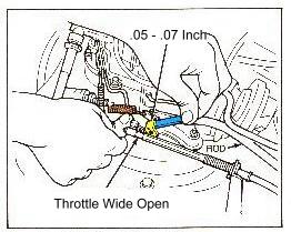
1. Check for binding (Figure 65). Move the rod down by hand as far as it will go. Check that the valve spring moves it back when you release it. 2. Check for proper setting (Figure 66). The rod must not move until the throttle is almost wide-open. At wide-open throttle, the rod must still have some slight travel (.050.070 inch). BINDING OF THE ROD, A STICKING VALVE, OR ROD MISADJUSTMENT MUST BE CORRECTED BEFORE ROAD TESTING.
DOWNSHIFT LINKAGE ADJUSTMENT
I . Hold the throttle wide-open against its stop. 2. Push the rod down to force the downshift valve to bottom in the valve body. 3. Measure the clearance between the tip of the adjusting screw and the throttle lever. It should be .050 to .070 inch. 4. Turn the screw as required to obtain this clearance.
Band Adjustments
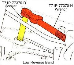
QUICK CHECKS The bands can be quick-checked before the road test as follows: 1. Be sure the oil level is correct. 2. Shift the selector to positions R and 2, and check for firm engagement. * If engagement in R is delayed or mushy, adjust the rear (low-reverse) band. * If engagement in 2 is delayed or mushy, adjust the front (intermediate) band.
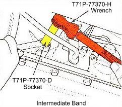
1. Loosen the adjuster stop. 2. Remove and discard the locknut. Install a new nut loosely on the stop. 3. Tighten the screw to 10 foot pounds torque; or until the adjuster wrench overruns. (All the special adjuster tools click and overrun at 10 foot pounds.) 4. Back the screw off exactly the specified number of turns: intermediate band, 41/4 turns; low-reverse band, 3 turns. 5. Hold the adjustment and tighten the new locknut- 35 to 45 foot pounds. 6. Road test the car. If the complaint isn't corrected, air test the servo. NEUTRAL START SWITCH
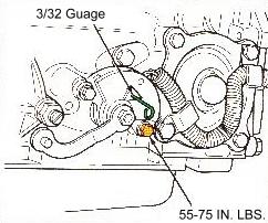
1. Put the selector in Neutral and hold it there. 2. Loosen the switch bolts. 3. Insert a 3/32 gauge pin or a drill through the hole in the switch. Wiggle the switch until the drill seats in the case. 4. Tighten the bolts 55-75 inch pounds and remove the drill.
ROAD TEST DIAGNOSIS
A properly conducted road test is really your most valuable diagnosis tool if you know your transmission and apply this knowledge. It will tell you if any of the drive train holding members are slipping; and will usually give a clear indication of valve body and governor functioning. Figure 70 is a chart of what to check for on the road test. You can duplicate it to record test results. You can also use the Diagnosis Check Sheet in booklet 1701-204.
There are specifications published for automatic shift speeds in three operating conditions in D range: 1. The minimum throttle shifts check the operation of the shift valves and governor circuit. 2. The to-detent or torque demand shifts check the throttle valve systems delay of upshifts and boost of control pressure. ("To detent" is almost full throttle . . . just before the downshift rod starts to move.) 3. The through-detent or wide-open throttle shifts check the downshift (kickdown) system, with the downshift valve actuated. TEST PREPARATIONS NOTE: Shift speed testing can be done in the shop, but will give no indication of shift "feel". A road test is preferable. To prepare for the shift speed test: 1. Look up the specifications for shift speeds for the particular engine, transmission and axle combination. Write them on the check sheet. (Record the actual shift speeds during the test for analysis following the test.) 2. Depress the accelerator a time or two to get the feel for where kickdown is actuated. (Some technicians put an extra spring or rubber band on the downshift rod to help "feel" when it moves.) Be sure to observe the following procedures and analysis for each of the tests: and always pay attention to the "feel" of the shifts as well as the shift speeds. MINIMUM THROTTLE UPSHIFTS To check the minimum throttle upshifts, give it just enough gas to barely accelerate the vehicle. Specifications call for above 12 inches of vacuum for all minimum throttle shifts. That means throttle pressure should be low - not enough to raise control pressure or to cause modulated throttle pressure to act on the 2-3 shift valve to delay upshifts. When you move the selector to D, the forward clutch and governor supply system is charged with control pressure. The clutch applies, and with the one-way clutch holding, you are in first gear. Control pressure to the governor is dead-ended at the governor valve, so that there is no governor pressure. As you drive off in first gear, you can be fairly sure the governor valve is not stuck in the maximum pressure position. If it was, the governor pressure would build up immediately, causing an immediate upshift to second. MINIMUM THROTTLE 1-2 When you reach about 10 mph, governor pressure should cause a shift. Since control pressure opposing the governor is low, the 1-2 shift valve moves to charge the servo apply system. A smooth 1-2 shift at 12 mph tells you the governor and 1-2 shift valve are free; and that the servo is applying the band. If the band doesn't apply, you'll stay in first gear and upshift to third at a higher speed. MINIMUM THROTTLE 2-3 Without increasing the throttle setting, check for the 2-3 upshift at specified speed. Now, governor pressure has risen high enough to overcome the 2-3 shift valve spring. (There is still no modulated throttle pressure.) The 2-3 shift valve moves and charges the reverse-and-high clutch system. The clutch is applied and at the same time release pressure on the servo releases the band. The governor is still doing its job, the clutch circuit is hydraulically tight, and the 2-3 shift valve is free. COASTING DOWNSHIFTS Let the vehicle "coast down" in D range. When the governor primary valve moves (about 10 MPH), governor pressure goes to zero. The shift valves move simultaneously to downshift 3-2 and 2-1. In first gear, the car should be free-wheeling. "TO-DETENT" SHIFTS The "to-detent" upshifts are full-throttle shifts. Throttle pressure is maximum, and acts on the modulator valve so maximum modulated throttle pressure is available to delay the 2-3 upshift and high control pressure to delay the 1-2 shift. There is no downshift valve input to the shift valves. UPSHIFTS If the upshift points are within specifications and the shifts are firm, the throttle valve and throttle modulator valve are operating freely. Also, the governor still is doing a good job. 3-2 SHIFT At about 25 mph in high gear, push the accelerator "to the detent." This raises modulated throttle pressure enough to force the 3-2 shift. "THROUGH-DETENT" SHIFTS Check the through-detent upshifts by pushing the accelerator to wide open throttle in D and holding it there. Check the kickdown shift points by pushing the accelerator through the detent at the appropriate road speed. These shift points are a check on the downshift valve and on the governor pressure output above 10 MPH. TEST RESULTS/CONCLUSIONS After the road test, determine what repairs are needed by analyzing what's going on during the problem shift. You can "dial" the test results onto the slidewheel to determine what to do next. Here are some tips on road test analysis. Governor - It is okay if shift speeds are all okay. If they aren't, refer to Governor Test and Inspections in this section. Valve Body - The problem may be correctable by cleaning the valve body or tightening its bolts to the specified torque. Throttle Valve and Diaphragm - Perform the checks in this section if the shifts are early and mushy or harsh and delayed. Bands and Clutches - Use the Application Summary Chart on page 33 (and on back of the slidewheel) to analyze whether any holding member is slipping. If a band slips, adjust it and drive the vehicle again. Further diagnosis can be made by the line pressure test and case air pressure tests. STALL TEST
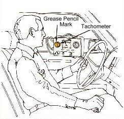
1. Look up the specified stall RPM for the vehicle. Use a grease pencil to mark the RPM on the dial of a tachometer. 2. Connect the tachometer to the engine and position it for easy reading from the driver seat (Figure 71)
IMPORTANT: If the needle goes past the mark, something is slipping. Release the accelerator immediately. 4. Record the results in each range (high, low, or OK) 5. Run the engine at fast idle, in neutral, between each test to cool the fluid. 6. Refer to Figure 72 for further checks or corrective action to take.
Line (control) pressure testing is often called for on shift complaints; and may be useful in diagnosing slip conditions. Where ordinary checks of the T. V. system do not disclose the cause of the condition, the pressure test will pinpoint it to other parts of the transmission; such as the pump or valve body. PREPARATION
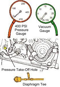
I . Attach a 400-psi gauge with a long hose to the pressure take-off at the left front of the case (Figure 73). Put the gauge where you can see it from the driver seat (Figure 71). 2 . Look up the control pressure specifications and write them on your diagnosis guide sheet or a chart as shown in Figure73. 3. If a vacuum bleed valve is available, tee it into the diaphragm vacuum line. This will let you simulate heavy throttle conditions without operating at stall. If a bleed is not available, tee in an ordinary vacuum gauge, such as on the automatic transmission tester. NOTE: The hand vacuum tester 21-0014 ( The hand vacuum tester 21-0014 ( The hand vacuum tester 21-0014 ( The hand vacuum tester 21-0014 (Figure 61) has a bleed valve and vacuum gauge. TESTING The stall test can be performed at the same time as the pressure test. The procedure following is for the stall method. If you use a vacuum bleed, run the engine at 1000 RPM for the 10 inches and WOT readings. 1. At idle, with vacuum above 12 inches, record the control pressure in all selector positions. NOTE: Apply the parking and service brakes firmly for each test. Do not operate at stall longer than 5 seconds; just long enough to get a reading. Operate the engine in neutral at fast idle between tests for cooling. 2. Perform the test at 10 inches of vacuum in the forward ranges and record the results. 3. Perform the wide-open throttle tests in D, 2, 1 and R and record the results. TEST RESULTS/CONCLUSIONS The "road map" chart (Figure 74) shows the likeliest causes of out-of-spec pressure readings in various ranges. In some cases, low pressure can be caused by internal leakage in the clutch or servo circuits. To verify the leakage, remove the valve body and air test the circuit(s) Here are some additional tips on analysis of the control pressure test. LOW PRESSURE AT IDLE - Low pressure at idle only is usually caused by low pump output, an internal leak, or a sticking regulator valve. Check the pump inlet screen, oil pan filter and valve body bolt torque. Other causes require major repair procedures. HIGH PRESSURE AT IDLE - High pressure at idle means there is probably T. V. input to the pressure regulating system. Check out the throttle valve, diaphragm and vacuum system. If they're okay, the valve body may need to be serviced. HIGH OR LOW IN ALL TESTS - Very rarely, the pressure will test high or low in all the conditions. This can be corrected by replacing the T.V. diaphragm control rod with a longer or shorter selective rod. Changing the rod length changes the regulating pressure of the throttle valve. IMPORTANT: SEE THE SHOP MANUAL FOR TMS PROCEDURE. NEVER CHANGE THE SETTING JUST TO SOFTEN THE SHIFT FEEL; ONLY TO MEET SPECIFICATIONS. PRESSURE OKAY IN ALL TESTS - It may be time to stop the diagnosis process. If the fluid levc], linkage, shift speeds and pressure tests check out OK, the transmission is OK. Certain "shift feel" conditions then am due to "driveability" characteristics; and no further should be made to diagnose the transmission. GOVERNOR TEST - The governor is normally "okayed" on the road test, if all the shift points are to specification. If they are not, a governor test can be performed either in the shop or on the road to determine if the governor is functioning. The test is based on the fact that governor pressure acts on a cutback valve in the valve body to reduce control pressure with increased road speed. If the pressure "cutback" doesn't happen the governor or valve body may be at fault. TEST PREPARATION
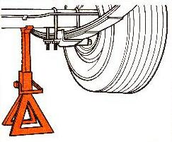
2. In the shop, raise the vehicle slightly. Support it on jack stands to permit the rear wheels to turn (Figure 76). 3. Look up the cutback "road speed" specification. TEST
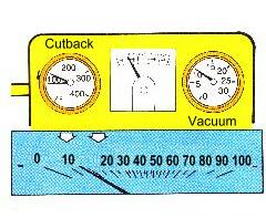
2. Slowly accelerate in range 2. 3. Watch for a pressure cutback at between 10 and 13 MPH. 4. Record the "road speed" at which the cutback occurs. TEST RESULTS * Cutback speeds okay - Governor is okay. * Cutback is early or late - Inspect governor and screen. If okay, check cutback valve in valve body.
Governor Inspections
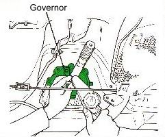
GOVERNOR IN-CAR INSPECTION
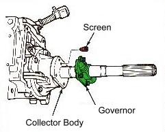
2. Check the mounting bolt torque (Figure 78). It should be Figure 78 - Tightening Governor Bolts 80-120 inch pounds. If not, tighten the bolts correctly and recheck for sticking. GOVERNOR SCREEN
2. Remove the screen (Figure 79). Check it for contamination. If it's severely contaminated, so is the forward clutch COLLECTOR BODY circuit. Remove the oil pan for fluid inspection. 3. Clean and replace the screen. GOVERNOR BENCH INSPECTION
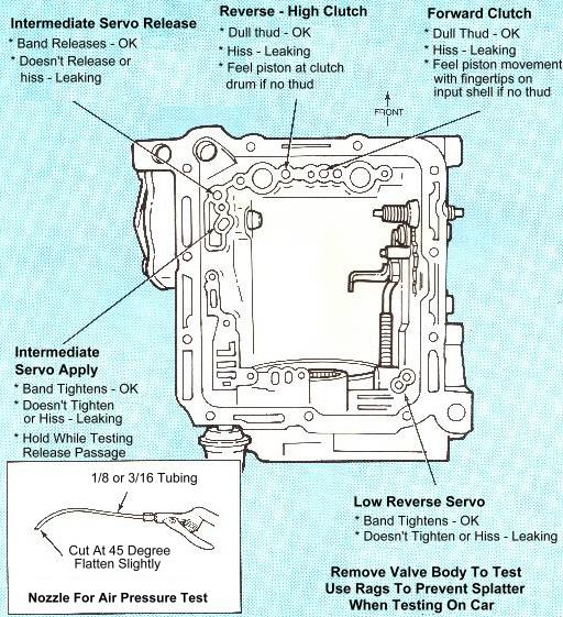
2. Check sticking valves for buffs. 3. Remove burrs by rolling on an Arkansas Stone. 4. De-burr valve bore with rolled crocus cloth. 5. Assemble and install the governor. CASE AIR PRESSURE TESTS
inspecting the seals during disassembly. (The servos can be repaired on-car; clutches require bench overhaul.) If the circuit doesn't leak, the problem is mechanical. Refer to the Overhaul Flip Chart for a detailed procedure for these tests.
|
|||||||||||||||||||||||||||||||||||||||||||||||||||||||||||||||||||||||||||||||||||||||||||||||||||||||||||||||||||||||||||||||||||||||||||||||||||||||||||||||||||||||||||||||||||||||||||||
|
|