
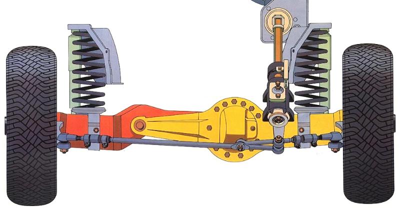
If you own a 1983-1997 Ford Ranger or Bronco II 4×4, knowing how to repair and rebuild your Dana 28 or Dana 35 front TTB axles is essential, especially if you do off-roading or heavy-duty trail driving. This guide walks you step-by-step through removing, inspecting, and replacing axle shafts, hubs, spindles, carriers, and slip yokes, with detailed photos and tips to avoid damaging components.
In this tutorial, you’ll learn how to:
- Remove and install front axle shafts for Dana 28 and Dana 35 TTB axles
- Disassemble and reassemble hubs, spindles, and wheel bearings
- Remove and reinstall carriers and slip yokes safely
- Properly inspect, grease, and install seals, bearings, and U-joints
- Identify common issues and avoid mistakes during axle maintenance or rebuilds
This guide is ideal for Ford Ranger and Bronco II owners performing a DIY axle rebuild or maintenance. For more details on related front axle projects, see our Dana 28 / 35 TTB Front Axles overview, Axle Pivot Bushing Replacement, and Dana 35 TTB Hybrid articles.
Introduction
The Dana 28 axle assembly can break under severe off-roading, and while the Dana 35 is stronger, it is also prone to failure under extreme conditions. This page shows you how to remove and replace axle shafts, inspect components, and rebuild your front TTB axles to keep your Ford Ranger or Bronco II 4×4 in top working condition. You’ll also learn what spare parts to carry when off-roading for a reliable trail repair.
Removing the Wheels, Hubs & Spindles
Step 1) Loosen the front wheel lug nuts.
Step 2) Raise and safely support the front of the vehicle.
Step 3) Remove the lug nuts and wheel/tire assembly.
Step 4) If equipped, remove the lug nut retainer washers from the wheel studs.
Step 5) Remove the manual locking hub assembly from the rotor by pulling straight outward.
Step 6) Remove the disc brake calipers and support the caliper on the vehicle’s frame rail. Remove the front brake calipers by removing the caliper retaining pin and slide off the caliper. You will probably have to remove the pin by squeezing it with pliers to fit in the groove and then driving it out with a punch and a hammer. Hang the caliper out of the way with wire to avoid any strain on the brake line.
Step 7) Remove the locking hubs, wheel bearings & locknuts:
Step A) Remove the retaining washers from the wheel stubs and remove the locking hub.
Step B) Remove the snap ring, axle shaft spacer, and bearing spacer.
Step C) Remove the lock nut with a (4) prong hub tool.
Step D) Remove the inner wheel bearing lock nut and wheel bearing.
Step 8) Remove the nuts (15mm) retaining the spindle to the steering knuckle. Tap the spindle with a plastic or rawhide hammer to jar the spindle from the knuckle.
Removing The Shafts
Step 1) Remove the left-hand side axle shaft by pulling the assembly out of the carrier and through the hole in the steering knuckle (spindle mount).
NOTE: The left-hand axle shaft is engaged inside of the front carrier assembly. Depending on how the truck is sitting (especially if it is not level), some fluid may leak out of the front carrier assembly. A small drip pan should be placed underneath the front carrier as a precautionary measure.
Step 2) Remove the right-hand axle shaft by performing the following:
Step A) Remove and discard the right front axle joint boot clamp from the outer axle assembly.
Step B) Pull the right-hand axle shaft out of the axle joint boot and stub shaft and through the hole in the steering knuckle (spindle mount).
Replacing The Shafts:
Step 1) Install the right-hand axle shaft as follows:
Step A) Ensure that the rubber boot is properly installed on the carrier stub shaft. Slide a new outer axle shaft boot clamp onto the rubber boot.
NOTE: The Dana 35 front axle does not use blind, or master, splines. Therefore, special attention should be made to ensure that the yoke ears are in line (in phase) during assembly. The Dana 28 splines will only fit one way.
Step B) Slide the right axle shaft assemble through the hole in the steering knuckle, into the rubber boot and engage the splines of the stub shaft. Ensure the splines are fully engaged.
Step C) Position the rubber boot and clamp onto the outer axle shaft and crimp the clamp securely on the rubber boot using Keystone Clamp Pliers T63P-9171-A.
Step 2) Install the left-hand axle shaft by sliding it through the hole in the steering knuckle and engaging it into the carrier. Ensure that the shaft is fully seated into the carrier and engage to the splines inside.
Step 3) Install the front disc brake rotor shield, spindle (make sure spindle bearing is greased and in good condition) and retaining nuts. Tighten the spindle nuts from 35-45 ft-lbs.
Step 4) Install the front brake rotors, bearings (make sure the bearings are greased and in good condition), locknuts, inner shaft spacer (looks like a splined thin washer) and snap ring.
Step 5) Install the hubs.
Step 6) Install the brake caliper and retaining pin
Step 7) Install the wheel assembly.
Step 8) Lower the vehicle. Tighten the lug nuts to specification.
| Dana 28 Part Numbers | |||
| Part # | Application | Brand | Description |
| SBK-2 | Dana 28 | Federal Mogul | Axle hub and axle bearing and seal kit. (2) needed to do both sides. |
| 8321 | Dana 28 | Federal Mogul | Rotor Seals. (2) needed to do both sides. |
| W35-3543 | Dana 28 | Federal Mogul | Right side Dana 28 differential to axle seal. |
| 710065 | Dana 28 | Federal Mogul | Left side Dana 28 differential to axle seal. |
| E3TZ-3249-A | Dana 28 | Ford | Axle U joints. (3) needed to do both sides. See Note 1 |
| Note 1 Some aftermarket U joints will not fit due to machining differences. | |||
For more part numbers and information, check out:
Removal Of Carrier And Slip Yoke:
Step 1) Jack up the vehicle, secure it on jack stands, and remove the front wheels.
Step 2) Remove the nuts and U-bolts connecting the driveshaft to the yoke.
Step 3) Remove the spindles and axle shafts as described above.
Step 4) Place a jack under the carrier. Remove the bolts securing the carrier to the support arm. Separate the carrier from the support arm and drain the carrier.
Step 5) Rotate the slip yoke and shaft assembly so the open side of the snap ring is exposed. Remove the snap ring from the shaft.
Step 6) Remove the slip yoke and shaft assembly from the carrier.
Step 7) Remove the oil seal and caged needle bearing.
Installation:
Step 1) Clean and inspect the bearing bore. Drive the bearing in until it’s fully seated in to the bore.
Step 2) Coat the oil seal with multi-purpose grease and drive it in to the carrier housing.
Step 3) Install the slip yoke and shaft assembly into the carrier so that the snap ring groove in the shaft is visible.
Step 4) Install the snap ring in the groove and make sure it is completely seated in the groove.
Step 5) Clean all traces of gasket sealant from the mating surfaces with lacquer thinner or gasket remover. Apply RTV sealant in a 1/4 inch wide bead. The bead should be continuous and not pass through or outside the holes.
Step 6) Position the carrier on the transmission jack and install it in to position on the support arm. Use the guide pins for alignment. Install and tighten the bolts to 40-50 ft. lbs.
Step 7) Install the shear bolt securing the carrier to the axle arm and tighten to 75-95 ft. lbs.
Step 8) Install the shaft, joints, and spindles.
Step 9) Connect the driveshaft. Tighten the U-joint straps to 8-15 ft. lbs.
Step 10) Fill the carrier with Hypoid lubricant. Trak-Lok limited slips add 4oz. of friction modifier.
Step 11) Install the front wheels.
Full Exploded Views (.pdf)
Related Articles
1983-1997 Ford Ranger 4×4 Dana 28 & Dana 35 TTB Front Axles
Last Updated:
About The Author
Jim Oaks is the founder of TheRangerStation.com, the longest-running Ford Ranger resource online since 1999. With over 25 years of hands-on experience building and modifying Ford Rangers — including magazine-featured builds like Project Transformer — Jim has become one of the most trusted authorities in the Ford Ranger off-road and enthusiast space.
Since launching TheRangerStation.com, Jim has documented thousands of real-world Ranger builds, technical repairs, drivetrain swaps, suspension modifications, and off-road adventures contributed by owners worldwide. TheRangerStation.com has been referenced in print, video and online by enthusiasts, mechanics, and off-road builders looking for practical, and experience-based information.