|
|
|
|
|
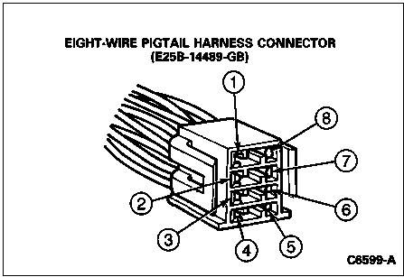
There are three wiring connectors connected to the electronic control module: the eight-wire pigtail harness connector; the five-wire harness connector; and the eight-wire harness connector. To check the integrity of these circuits, disconnect the harnesses from the electronic control module and perform the following checks. Eight-Wire Pigtail Harness Connector 1. Connect a voltmeter between terminal 8 and ground. The voltmeter should indicate battery voltage at all times. 2. Connect a voltmeter between terminal 7 and ground. Then turn the ignition switch to the RUN position. The voltmeter should then indicate battery voltage. CAUTION: In the following sections where the usage of an ohmmeter is specified, always remember that an ohmmeter should NEVER be connected into a "live" or powered circuit. If the ohmmeter is subjected to a powered circuit, severe damage will be done to the meter. The vehicle's battery should be disconnected before performing checks on any circuit with an ohmmeter to prevent any accidental damage to the meter. 3. Connect an ohmmeter between terminal 6 and ground. The ohmmeter should indicate a low resistance value (less than 10 ohms). 4. Connect an ohmmeter between terminals 4 and 5 of the wiring harness connector. The ohmmeter should indicate a low resistance value (less than 10 ohms). 5. Connect an ohmmeter between terminal 3 and ground. The ohmmeter should indicate zero ohms. 6. Connect an ohmmeter between terminal 2 and ground. The ohmmeter should indicate zero ohms.
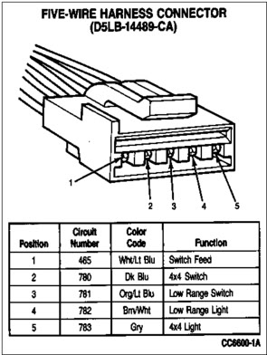
Five-Wire Harness Connector 1. Connect an ohmmeter between terminals 1 and 2. Then depress the 4x4 (2H-4H) switch. The ohmmeter should indicate a low resistance value (less than 50 ohms) while the switch is being depressed. 2. Connect an ohmmeter between terminals 1 and 3. Then depress the LOW RANGE switch. The ohmmeter should indicate a low resistance value (less than 50 ohms) while the switch is being depressed. 3. Connect a test lead between terminal 4 and ground. Turn the ignition switch to RUN and observe the indicator lights. The LOW RANGE light in the instrument panel and LOW RANGE indicator light on the switch should illuminate. 4. Connect a test lead between terminal number five and ground. Turn the ignition switch to RUN and observe the indicator lights. The 4x4 light in the instrument panel and 4x4 light on the switch should illuminate.
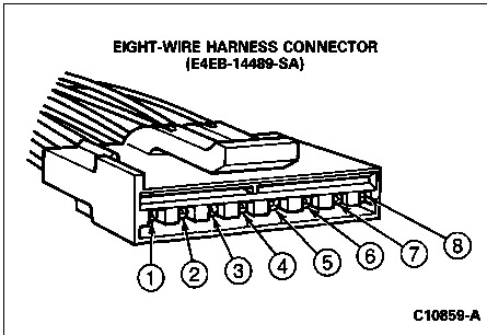
Eight-Wire Harness Connector 1. Connect an ohmmeter between terminal 1 and ground. On a vehicle equipped with a manual transmission, depress the clutch pedal and observe the ohmmeter. The ohmmeter should indicate a low resistance (less than 50 ohms) while the clutch pedal is being depressed. If the vehicle is equipped with an automatic transmission, shift the transmission into NEUTRAL and observe the ohmmeter. The ohmmeter should indicate a low resistance (less than 50 ohms) while the transmission selector lever is in the NEUTRAL position. 2. Connect an ohmmeter between terminals 2 and 3. The Ohmmeter should indicate a low resistance reading (225-275 ohms). This will check the continuity of the speed sensor that is located in the transfer case. The speed sensor picks up the rotating speed of the transfer case rear output shaft from two notches that are cut in opposite sides of the outer ring of the clutch housing assembly.
|
|
|