|
Start
by draining the fluid and removing the inspection cover. Support
the rear axles with jack stands and remove the tires. |
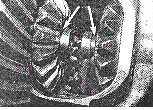
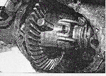
Remove the pinion shaft from the carrier.
At this point you should be able to remove the spider gears from the carrier. |
The C-Clips are retained in small grooves at the axle shaft tips.
Push the axles inward to remove the clips. Pull the axle shafts out a few inches and remove the side gears.
|
|
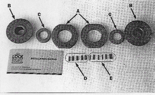
Coat the teeth of the couplers, drivers and the outer surface of the spacers with
medium grease. The grease helps hold everything in place during the installation. |
Two thrust washers should have been removed from the carrier with the original gears. These are reused. |
Two small slotted holes are in each driver for the shear pins.
Put a little
grease in each hole and then insert the pins until they are flush with the drivers. |
|
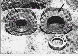
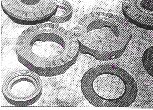
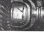
The spacers ride inside he drivers, and each spacer has a recessed and a flat edge.
The recessed edges of the spacers point in the same direction as the teeth on the drivers, as shown on the left.
It's important that the spacers are pointing in the correct direction. |
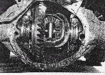
Now your ready to install the pieces in the carrier.
Start by inserting the couplers in the carrier and slide the axleshafts through them.
Install a C-Clip on the left axleshaft with the open end pointing down.
Pull firmly on the left axleshaft to seat the clip. |
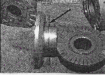
Place a driver and spacer inside the carrier and line up its teeth with the left coupler.
Push firmly on the spacer to make sure it seats over the C-Clip.
The backside of the spacer should be flush with the end of the
axleshaft. |
|
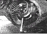
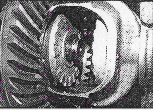
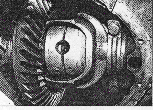
Now comes the tricky part.
Place the second driver in the carrier and center it with the left driver that's already installed.
Using a stiff wire, push the spacer on the right driver to the left to help hold it temporarily in place. |
Carefully rotate the left axleshaft until the C-Clip groove in the right side driver teeth is visible and accessible through the carrier. Place the remaining C-Clip in the groove with its open end facing toward the tip f the
axleshaft. Once its in place, firmly pull on the right wheel hub to seat the clip. Rotate it 1/4 turn forward so the open end of the C-Clip points downward. |
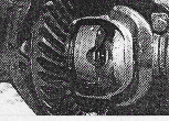
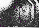
Rotate the left axleshaft so that both circular recesses on the drivers are pointed toward you.
Push the right driver toward the right coupler and mesh the
teeth through the circular recess, push the spacer in the right driver over the C-Clip and
axleshaft. |
|
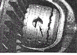
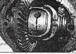
Rotate the drivers until a slotted hole on the right driver lines up with a shear pin hole on the left driver.
Use a small screwdriver to push the shear pin out of the slotted hole and into the hole in the left driver.
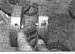
Take one of the
spring assemblies (The small spring inside the larger spring) and place one end of it in the slotted hole, and compress the springs until they are totally seated in the hole.
|
Repeat the directions (From the left) on the other pins and springs.
Once your finished, double check that the springs are seated by rotating the drivers and pushing on the springs with a small screwdriver. |
Rotate the carrier until the pinion shaft holes in it are lined up with the circular holes in the Lock-Rite and then install the pinion shaft.
It should slide easily in to place. Make sure the small retaining pin hole in one end of the pinion shaft lines up with the carrier and install the pin.
Check the operation of the Lock-Rite according to the directions. Seal & fill the housing and your ready for the trail! |