
- Joined
- Aug 10, 2014
- Messages
- 503
- Reaction score
- 22
- Points
- 18
- Age
- 31
- Location
- Madison, IN
- Vehicle Year
- 1995
- Make / Model
- Ford Ranger
- Engine Type
- 4.0 V6
- Engine Size
- 4.0L
- Transmission
- Automatic
- 2WD / 4WD
- 2WD
- Tire Size
- 215/70R15
A couple years ago I scored a 2-speed Taurus fan for virtually free (Goodwill, of all places, $2.50), and now that I've finally gotten to upgrading the alternator (130A), I'm looking at working on the swap. I'm mainly going for fuel economy, but any power/torque gains are icing on the cake.
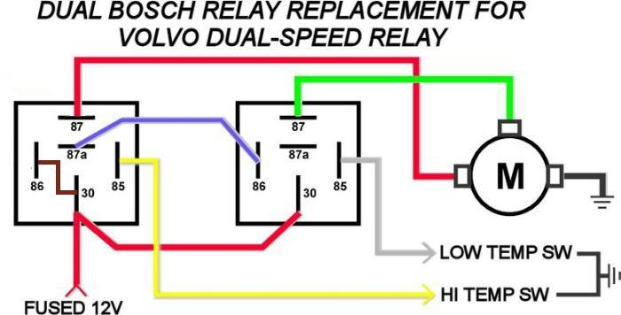
I'm planning on using a BMW switch (the 195/210 kind, to compliment my 195 T-stat) and doing my own relay circuit. I already have a crude schematic sketched which incorporates the A/C and when the A/C is on, keeps low speed on until the 195 switch trips, which will then turn on high; with the A/C off, the low will turn on at 195, and the high at 210, as usual. However, it makes some assumptions that I'd like to verify are true before buying more parts:
1. The BMW swiches are non-polarized? I'd like to use them as a high side switch, instead of a low side switch. This matters as it makes the A/C input a lot easier to implement (I can do all I want with three Bosch relays and a diode). All the schematics I see have the switch used on the low side, which I presume is to maintain compatibility with the often-used Volvo relay module, not because of the switches having some sort of diode protection or a chassis connection? I see the common terminal of such BMW switches on some schematics marked as "+", which leads me to believe it can be used in such a way.
2. The Taurus fan is only powered by one input at a time, right? Not both for high speed? This isn't as important, as all it changes is one relay connection: whether the low temp relay's common needs to be powered off the NC terminal of the high temp relay, or gets tied to the fused fan power like the high temp relay common.
3. For adding the BMW sensor, my plan is to get one of the aluminum radiator hose adapters with a 1/8 NPT hole, and then drill and tap it for the M14x1.5 the sensor uses. This will ensure the sensor has good contact with the coolant flow. I was planning to add it to the "over the alternator" part of the upper hose, which would allow me to also use it as a coolant fill bleed point if I so wished. Is this a good place to put the sensor (rad outlet), and is the 195/210 switch the correct one to use in conjunction with my 195 degree thermostat? If not a good place, where would be better?
If there is interest/relevance, I'll scan and upload my schematic sketch.


