• Welcome Visitor! Please take a few seconds and Register for our forum. Even if you don't want to post, you can still 'Like' and react to posts.

Has anyone successfully recalibrated the speedo on a 98-00 ranger?


cmequestionu

Member
Solid Axle Swap
Joined
Nov 6, 2008
Messages
154
Reaction score
16
Points
18
Location
Federal Heights, Colorado
Vehicle Year
2000
Make / Model
Ford Ranger
Engine Type
4.0 V6
Engine Size
4.0
Transmission
Automatic
2WD / 4WD
Solid Axle Swap 4x4
Total Lift
~10
Tire Size
35
I've purchased a Jet reprogrammer. There was no option to adjust the speedometer, I called Jet and they told me my firmware was out of date so I went to Ford and had it updated to no avail. Then I actually took it to Ford to see if they would do it and they told me there were only set groups of tire/gear ratios and my truck is currently outside those ranges(4.56 gear, 35" tires).

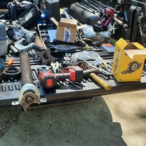
This led me to this product called yellow box from Australia. It's a device that is supposed to act as a digital gear reducer. But after hooking it up all I got was a trouble code. I tried the abs signal and the PCM to instrument panel wire.

I checked the forums here but all the products listed are no longer available. On a side note, if any one needs a speedometer recalibrater I have one to sell. Go to yellr.com to find out more.


RonD

Official TRS AI
TRS Technical Advisor
Joined
Jun 2, 2012
Messages
25,363
Reaction score
8,372
Points
113
Location
canada
Vehicle Year
1994
Make / Model
Ford
Transmission
Manual
The GEM module calibrates the speedometer on 1998-2000 Rangers unless it has 4WABS then the ABS module does it
They both use Revolutions per mile as the calibration, so you need that number from tire size calculator

Either can be reprogrammed by a dealer for new tire size

Or info here on DIY with a programmer: https://www.explorerforum.com/forums/index.php?threads/gem-module-reconfiguration-computer-flashing.134477/

The Dakota Digital SGI-5E is a little cheaper than the yellow box, for the same thing, just $10 cheaper, but it is $10, lol
 

cmequestionu

Member
Solid Axle Swap
Joined
Nov 6, 2008
Messages
154
Reaction score
16
Points
18
Location
Federal Heights, Colorado
Vehicle Year
2000
Make / Model
Ford Ranger
Engine Type
4.0 V6
Engine Size
4.0
Transmission
Automatic
2WD / 4WD
Solid Axle Swap 4x4
Total Lift
~10
Tire Size
35
I worry that the Dakota Digital IS the same thing and I'll just have the same problem I'm having with the Yellow Box. I would like to hear from someone who has installed one on a 98-00 ranger.

I've tried the dealer option and they told me that they couldn't for whatever reason.
 

RonD

Official TRS AI
TRS Technical Advisor
Joined
Jun 2, 2012
Messages
25,363
Reaction score
8,372
Points
113
Location
canada
Vehicle Year
1994
Make / Model
Ford
Transmission
Manual
Do you have 4wheel ABS or just rear wheel ABS?

And are you doing this strictly for tire size change or was speedometer never accurate?

Also call up a larger tire shops, and ask, they may still have the handheld device used to reprogram GEM/ABS, it was a service they needed to offer

But surprise the Ford dealer wouldn't do it, quick cash for little work


To use either interface you would by-pass the GEM or 4WABS module, you can't use eithers OUTPUT signal as its too close to 8,000ppm to recalibrate
The interface would be spliced into the 2 wires from the rear axle ABS for IN signal to interface, 25,000ppm
The 8,000ppm OUT signal would then be connected directly to speedometer, old speedometer wire would be cut
The PCM and cruise can use the old incorrect signal without effecting performance/shifting, its not off by more than 10mph right?

But if you want you can connect OUT signal to the Feed wire from the GEM or ABS module, that would do all 3, speedo, PCM and cruise

Only humans use MPH
Cruise just uses PPM, i.e. if you set it at 6,000ppm then it tries to hold 6,000ppm, that could be 50MPH or 70MPH, it doesn't know or care
Same for PCM, just uses PPM for ratios in automatics, no MPH
 
Last edited:

cmequestionu

Member
Solid Axle Swap
Joined
Nov 6, 2008
Messages
154
Reaction score
16
Points
18
Location
Federal Heights, Colorado
Vehicle Year
2000
Make / Model
Ford Ranger
Engine Type
4.0 V6
Engine Size
4.0
Transmission
Automatic
2WD / 4WD
Solid Axle Swap 4x4
Total Lift
~10
Tire Size
35
The truck came stock with 4WABS. I say that because the Dana 44 I swapped in doesn't have abs tone rings. I modified the rear 9" to accept the tone ring because I knew it needed it for the speedometer/transmission/cruise. I would like to get my speedometer to read closer to the speed I'm actually traveling. I read 57 mph at 65 mph.

I tried hooking up the yellow box to the abs sensor on the axle but got no signal at all at the speedo. I read the wiring diagram and from what I understand there are two wires coming from the sensor. One reads the high, or the tooth of the ring, the other reads the low or the gap in between the teeth. The yellow box only corrects one "hall effect" type signal. I think the signal coming from the GEM may be a voltage based signal (more voltage = more speed) which is why it can't correct it. I have no way of testing this.
 

RonD

Official TRS AI
TRS Technical Advisor
Joined
Jun 2, 2012
Messages
25,363
Reaction score
8,372
Points
113
Location
canada
Vehicle Year
1994
Make / Model
Ford
Transmission
Manual
The rear axle sensor is VR(variable reluctance), it generates its own AC volt signal, so its not hall effect type which requires outside power to work

VR sensors generate a sine wave, AC voltage, that cycles above and below 0 volts, the volts are not important the cycling/frequency is
Hall effect is either 5v on/off, or 12v on/off, for its pulse count, so different type of signals, not interchangeable

One of the VR sensor's wires is grounded, because only the positive half of the sine wave is used as the Pulse count, use an OHM meter to test which one
That's why there is only 1 "speed" wire, grey/black, that runs to the devices using the corrected speed signal, these devices are already grounded, so they just need the corrected "+" PPM signal

Most interfaces are grounded by their 12v/ground connection, but best practice is to splice into both sensor wires and then hook them up to the - and + INPUT on the interface, just to be sure
But you only need the 1 OUT wire from interface to devices
 
Last edited:

RonD

Official TRS AI
TRS Technical Advisor
Joined
Jun 2, 2012
Messages
25,363
Reaction score
8,372
Points
113
Location
canada
Vehicle Year
1994
Make / Model
Ford
Transmission
Manual
EDIT

Just looking at Yellow box instructions, very confusing, since its for motorcycles

BUT........................you can't use it on the rear axle speed sensor

You have to use it on the CORRECTED signal coming from the 4WABS(or GEM)

So for speedo correction I think the easiest setup would be to use the current speedo wire on the back of the cluster as the IN "+" and then the OUT back to the speedometer

So
Cluster speedo "+" wire ---------(grey/black wire)------------Yellow box-----------(grey/black wire)--------------Speedometer
 
Last edited:

gw33gp

Well-Known Member
U.S. Military - Veteran
TRS Banner 2010-2011
Ham Radio Operator
Joined
Aug 7, 2007
Messages
1,736
Reaction score
538
Points
113
Location
Costa Mesa, CA
Vehicle Year
2002
Make / Model
Ford
Engine Type
4.0 V6
Engine Size
4.0 SOHC
Transmission
Manual
2WD / 4WD
4WD
Tire Size
33"
So for speedo correction I think the easiest setup would be to use the current speedo wire on the back of the cluster as the IN "+" and then the OUT back to the speedometer

So
Cluster speedo "+" wire ---------(grey/black wire)------------Yellow box-----------(grey/black wire)--------------Speedometer
That is the way I hooked up the Dakota Digital on my 02 Ranger. I am not sure the wire colors were the same but it sounds right. There is also a power and ground wire connected to the box.
 

adsm08

Senior Master Grease Monkey
Supporting Member
Article Contributor
Ford Technician
TRS 20th Anniversary
Joined
Sep 20, 2009
Messages
34,623
Reaction score
3,613
Points
113
Location
Dillsburg PA
Vehicle Year
1987
Make / Model
Ford
Engine Type
4.0 V6
Engine Size
4.0
Transmission
Manual
2WD / 4WD
4WD
Tire Size
31X10.50X15
But surprise the Ford dealer wouldn't do it, quick cash for little work
What he was told by the dealer is accurate. The current version of the IDS is locked down so that speedometer correction is done by entering the tire size and gear ratio, and you only have a list of the factory offerings to choose from.

The ONLY model I am aware of that can be programmed by pulse per mile or revolution per mile is the 1st gen Transit Connect, and even then only when doing a programable module installation or as-built programming of the PCM. If you simply go into the programable parameter you can only adjust the tire size, only one final drive ratio was offered in that vehicle.

OP, you need to find a tire or 4x4 custom shop that has an aftermarket unit capable of doing what you want, OR if you can find a pairing of factory tire size and gear ratio that gets you really close to what you need the dealer can program those in.

For example, a 235/70/15 with 3.73 gears is a close final drive ratio to your 4.56 and 35s.

A 205/75/15 with 3.55 gears is even closer.
 
Last edited:

cmequestionu

Member
Solid Axle Swap
Joined
Nov 6, 2008
Messages
154
Reaction score
16
Points
18
Location
Federal Heights, Colorado
Vehicle Year
2000
Make / Model
Ford Ranger
Engine Type
4.0 V6
Engine Size
4.0
Transmission
Automatic
2WD / 4WD
Solid Axle Swap 4x4
Total Lift
~10
Tire Size
35
Cluster speedo "+" wire ---------(grey/black wire)------------Yellow box-----------(grey/black wire)--------------Speedometer
That's how i had it hooked up. All I got was a p0500 trouble code which is a problem with the VSS signal.
OP, you need to find a tire or 4x4 custom shop that has an aftermarket unit capable of doing what you want, OR if you can find a pairing of factory tire size and gear ratio that gets you really close to what you need the dealer can program those in.
That might be something worth looking into.
 

RonD

Official TRS AI
TRS Technical Advisor
Joined
Jun 2, 2012
Messages
25,363
Reaction score
8,372
Points
113
Location
canada
Vehicle Year
1994
Make / Model
Ford
Transmission
Manual
Ratio doesn't matter on 1998-2000 Rangers, it only reads axle rotations so strictly tire size matters

It you read drive line/output shaft rotations then you need axle ratio involved

P0500 is not related to speedometer, it means the PCM/computer is not getting a speed signal.
You can get P0500 with a working speedometer
Or not get P0500 when speedometer doesn't work

If you get P0500 AND no speedometer then its usually a failed speed sensor

Below is 1998 4WABS wiring, 1999/2000 is the same

You can see the rear axle sensor connected to module, it sends IN approx. 25,000ppm(pulse per mile)
Then on pin 10 you can see the grey/black wire, thats the corrected speed signal of 8,000ppm going OUT to Speedo, PCM, cruise, also goes to GEM

You said you don't have a working ABS?
But speedometer worked and was just off 7-10mph?
 

Attachments

Last edited:

cmequestionu

Member
Solid Axle Swap
Joined
Nov 6, 2008
Messages
154
Reaction score
16
Points
18
Location
Federal Heights, Colorado
Vehicle Year
2000
Make / Model
Ford Ranger
Engine Type
4.0 V6
Engine Size
4.0
Transmission
Automatic
2WD / 4WD
Solid Axle Swap 4x4
Total Lift
~10
Tire Size
35
I had the yellow box tied into the gray/black wire coming from pin 58 on the PCM in the engine bay. This was listed as the VSS signal to the speedo. I confirmed this with a Ford mechanic. Tapping into this wire gave me the trouble code.
 

RonD

Official TRS AI
TRS Technical Advisor
Joined
Jun 2, 2012
Messages
25,363
Reaction score
8,372
Points
113
Location
canada
Vehicle Year
1994
Make / Model
Ford
Transmission
Manual
Did you tell Ford mechanic the year and model of the vehicle

In 1998 to 2000 Rangers pin 58 on PCM is the VSS signal IN from 4WABS or GEM(speed corrected signal), so cutting it would cause P0500

In 1998 to 2000 the speedo, cruise and PCM share the speed corrected signal from either the 4WABS module or if RABS then from the GEM
So those devices are the end users of the corrected signal, not the source of the signal

In 2001 Ford changed the system and used the OSS(output shaft speed) sensor on trans or transfer case, for the speed signal but it was corrected to 8,000ppm by the PCM and outputted(if thats a word, lol) on pin 68 to the speedo and cruise
So this may be what Ford mechanic was referring to

It reads like the 4WABS was working for corrected speed since speedo worked before and no P0500
So reconnect pin 58 wiring as it was
Then install the yellow box on the speedo grey/black wire only, as described above
 

cmequestionu

Member
Solid Axle Swap
Joined
Nov 6, 2008
Messages
154
Reaction score
16
Points
18
Location
Federal Heights, Colorado
Vehicle Year
2000
Make / Model
Ford Ranger
Engine Type
4.0 V6
Engine Size
4.0
Transmission
Automatic
2WD / 4WD
Solid Axle Swap 4x4
Total Lift
~10
Tire Size
35

RonD

Official TRS AI
TRS Technical Advisor
Joined
Jun 2, 2012
Messages
25,363
Reaction score
8,372
Points
113
Location
canada
Vehicle Year
1994
Make / Model
Ford
Transmission
Manual
In 1998-2000 Ranger with 4WABS, the grey/black wire comes FROM the ABS module, and has a splice that sends that signal to cluster(speedo), PCM(pin 58), Cruise module, and GEM(pin 9), they all use the same grey/black wire color

GEM used speed signal for 4WD, i.e. 4Low(0MPH) and maybe to lock the doors above 5mph

I would re-splice any cut wires and then confirm you have speedometer and no P0500 codes

Then try Yellow box again on speedometer OR on the grey/black wire from the 4WABS module
Edit: do not use Hall Effect settings, try inductive coil wiring diagram
This unit is set up to use square wave pulses(hall effect), Ford uses sine wave pulse, curved, hopefully inductive coil wiring will read those


EDIT:
Just read though that Justanswers thread
That mechanic had it right the first time, pin 58 is speed IN, goofed up in changing it to OUT, 58 was never out only IN, pin 68 was VSS OUT but only in 2001 and up Rangers

Then he said its Hall effect type, which it is not, it's a VR(variable reluctance) signal, these sensors generate their own AC voltage signal.
Since the first VSS in the late 1980's Ford has used VR sensors for speed, so not sure where he came up with Hall Effect, Ford did use it on some Cam sensors and Crank sensor on the 1994 and older 2.3l engines
So no chance of it working with Hall Effect setting/wiring on Yellow Box in any configuration
 
Last edited:

Sponsored Ad


Sponsored Ad

Staff online

Member & Vendor Upgrades

For a small yearly donation, you can support this forum and receive a 'Supporting Member' banner, or become a 'Supporting Vendor' and promote your products here. Click the banner to find out how.

Truck of The Month


Mudtruggy
May Truck of The Month

Recently Featured

Want to see your truck here? Share your photos and details in the forum.

Follow TRS On Instagram

TRS Events

25th Anniversary Sponsors

Check Out The TRS Store


Sponsored Ad


Sponsored Ad

Sponsored Ad


Amazon Deals

Top