lowspeedpursuit
Active Member
- Joined
- May 6, 2022
- Messages
- 206
- Reaction score
- 151
- Points
- 43
- Location
- DE
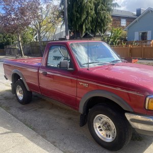
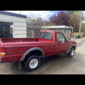
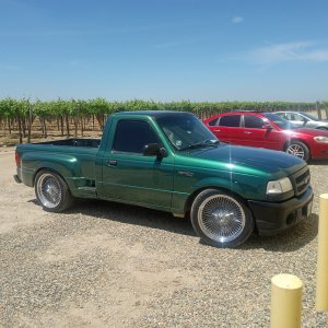
- Vehicle Year
- 1994
- Make / Model
- B2300
- Engine Type
- 2.3 (4 Cylinder)
- Transmission
- Manual
- 2WD / 4WD
- 4WD
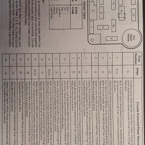
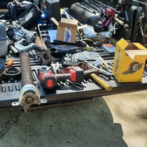
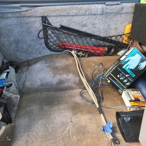
So since all the junkyards around here shut down--and a Rostra kit with everything is the better part of a thousand dollars--I'm installing cruise control the most backwards way possible: grabbing all the parts from different places and figuring out the connections myself. I'm taking pictures along the way, and I'll write it up at some point after the holiday, but for now I have a question about the amp, computer, whatever you want to call it. The green box that lives behind the glove box in '93/'94, possibly other years as well.
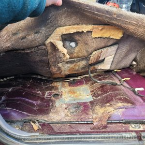
Does anybody have a good picture of the amp mounted in the stock location? Or even just a more detailed description than "it goes behind the glove box"? The manual shows the amp with the connectors facing left, and this amp came with a little bracket with two screw holes, but behind the glove box there's just nothing there it could attach to. I don't even really understand where it could go without the glove box bumping into it.
Thanks in advance.