enginepaul
Member
- Joined
- Aug 7, 2007
- Messages
- 426
- Reaction score
- 12
- Points
- 18
- Location
- Northern California
- Vehicle Year
- 1995, 2001, 200
- Make / Model
- Ford
- Engine Size
- 2.8
- Transmission
- Automatic
Everybody has figured this out by now (except me) but here are some notes:
Written September 2, 2017
My experience with replacing the CMP Cam position synchronizer on 1995 Ranger 4.0 California truck. This was done while replacing the heads so the heads and wiring harnesses were off.
First, I purchased a OTC T95T-12200-A Syncro Positioning Tool from Ebay and it does NOT fit. The outside diameter of the tool is the same as the positioner so it can't possibly work on my 95 because it can’t fit inside or outside of the synchronizer. I haven't tried it on a 3.0 or other years of the 4.0 so I can't speak to that.
I had much trouble pulling the unit from my block, far more than one would expect. I also had trouble placing the new unit into the hole; after several tries so I removed the hood to give me room to see from the driver's side. When the hood was off and I looked down to see the oil pump shaft leaning against the side of the hole, I put some grease in that part of the hole to hold the shaft away from the side. The unit then went in far enough to get the gears started with the next try.
I set the dampener 34mm past the TDC mark using a piece of tape marked at 34mm (One manual says some cranks have that mark from the factory.) before installing the new unit. I will try to post photos when I can find them.
I used the marks on the widow of the sensor so the tool wasn't needed in any case. I'm guessing he tool is used when you don't have the heads off on earlier versions, yet the manual still says it can be used and I couldn’t find an update anywhere that I looked. I couldn’t see the trailing edge or the rotor vane on my new unit so I removed the sensor and marked the trailing edge of the rotor vane with a silver sharpie. (The Bosch unit I removed had the trailing edge marked so it was easier to see.)
I decided to check the position using the method described in the Ford manual using the electrical set-up where you set it to where the voltage signals as the unit is rotated. That left the unit about 9 degrees counter-clockwise from where it would be using the window method. The unit I removed was in the same position as the window indicator line on my new unit, so the window mark is what I will use. VERY confusing! I certainly hope there is an update from the factory out there to clear this up; but our trucks are too old for Ford to care about.
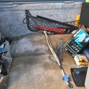
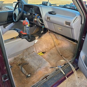
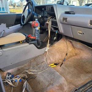
I didn’t use a factory test harness for the 12V signal, I just made a rig from what I had on hand.. I first used a meter, but then used a led light; the light was easier for me. Facing the unit when it is installed from the front of the truck, the left terminal is positive (+) the center terminal is the signal out, the right terminal is negative (-). I installed a shrink sleeve around the center (signal) terminal to be sure it didn’t short against the other two terminals. The positive and negative terminals were marked on my unit.
I bought a “CID Sensor Adjusting Wrench; T94T-12270-A” in case I need it for adjustments after the engine is put back together because I don’t want to even try to get a wrench in there after the heads are on.
Also, Ford says:
Rotate engine two revolutions to take up slack in timing chain and return to No. 1 cylinder to its compression stroke. (both valves closed)
NOTE: No. 1 cylinder must be at 26 degrees ATDC to set CID sensor. That would be 34mm or 1.34” past the TDC mark on the crank pulley. Crank rotates clockwise.
Rotate the CID sensor and stop at the exact point where the sensor switches from 0 to 12 volts on the voltmeter. In my case, that is when the led lights up.
>> The final movement to set the sensor must be in a counterclockwise direction.
Rotate the sensor clockwise past the CID switching point (from 12 to 0 volts).
Rotate the CID sensor counterclockwise and stop at the point the voltmeter switches from 0 to 12 volts. (Or when the led lights.)
Tighten the 10mm sensor hold-down bolt to 17-21 Nm (13-15 lb ft)
Last edited:


