The ECT like most sensors uses a pull down circuit(or pull up, lol) using 5 volts
This is why the voltage to resistance is reversed
At 60deg ECT should be at 58k ohms, and 3.5volts
At 180deg its at 4k ohms and 0.7volt
WTF!!!
Volts should go UP when resistance goes down, don't need an electrical degree to know that
But to understand a pull up, or pull down circuit you do, lol
I understand what it does but not enough to explain it, lol
Einstein once said, paraphrased, "if you can't explain something in simple terms to your Dear Mother then YOU don't understand it well enough"
In any case the computers circuit for the ECT sensor is not a simple voltage out/voltage in circuit
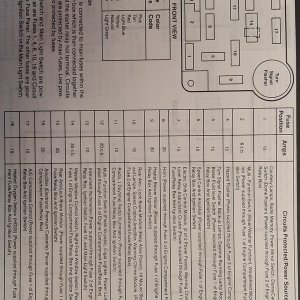
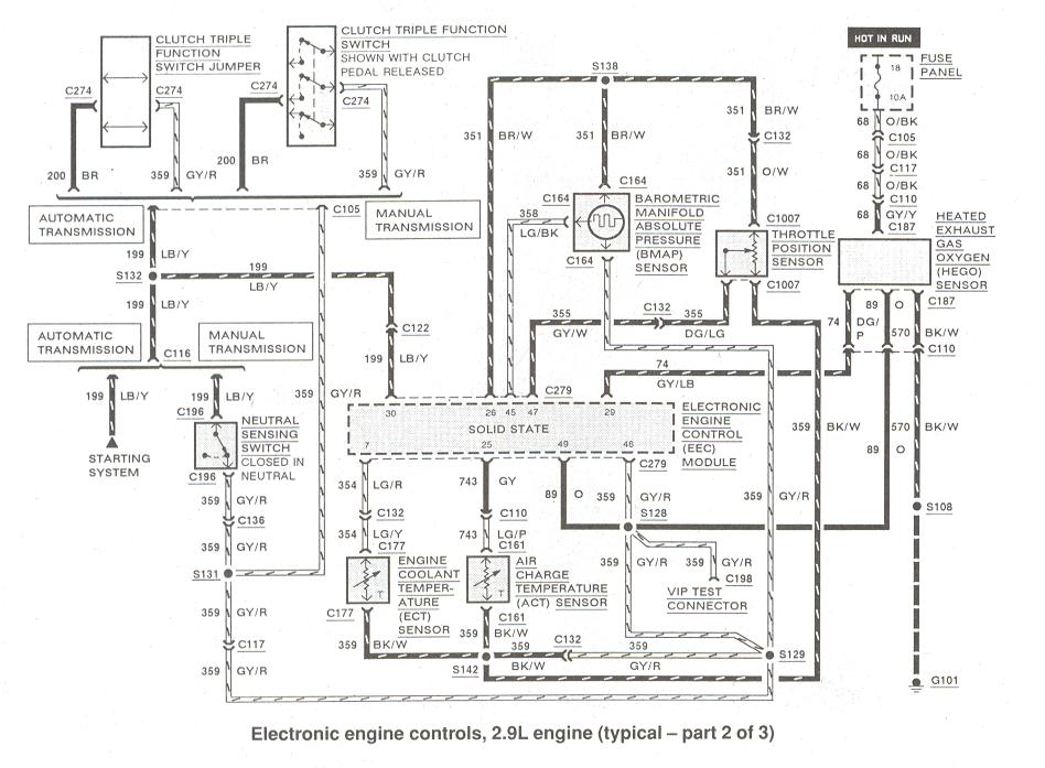
Pin 7 is the one for ECT, not sure why you don't see a wire there
2.9l wiring diagram here:
https://www.therangerstation.com/tech_library/EDiagrams/files/Diagrams_ElectronciEngControls2_9_2of3.JPG
Computer outputs 5volts from pin 26, and that is shared by almost all the engine sensors
At the ECT sensor it shows that 5volt wire as the black/white wire but can be another color as you can see its spliced and changes to a few other colors, lol
You can use a sewing needle to pierce a wire to test voltage, doesn't hurt the wire
So you can test for 5volt, but it should be fine since all the other sensors use that 5v but that one splice to ECT could be bad
Then test light green wire(out to computer) to see its voltage with engine cold and then warmed up


