• Welcome Visitor! Please take a few seconds and Register for our forum. Even if you don't want to post, you can still 'Like' and react to posts.

O2 Sensor Wiring


kxri318

Member
Joined
Jan 31, 2023
Messages
96
Reaction score
28
Points
18
Location
Ohio
Vehicle Year
1986
Make / Model
Ford Ranger
Transmission
Automatic
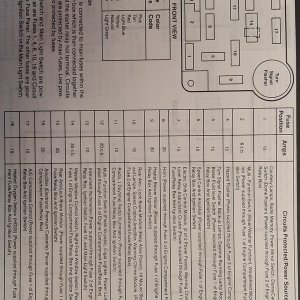
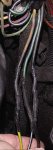
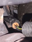
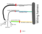
My O2 sensor connector melted so I had to get a new connector and I'm like 90% sure I have it wired right, but I want to double check. Can anyone tell me what color wires are for data and which are for the heater on a 1986 Ford Ranger w/ 2.9? The wires actually going to the O2 sensor from the wiring harness are yellow, green/blue, and black. The connector that I bought has a black/white wire for the data, a big black wire for one side of heater, and a yellow/green wire for the other side of the heater. I made a quick diagram to show how I have it connected rn.
 

Attachments


RonD

Official TRS AI
TRS Technical Advisor
Joined
Jun 2, 2012
Messages
25,363
Reaction score
8,372
Points
113
Location
canada
Vehicle Year
1994
Make / Model
Ford
Transmission
Manual
3 wire O2s just have 1 heater wire

One 12volt key on heater wire, O2s heater is grounded via the threads on exhaust pipe, a 4th Ground wire was added a few years later

Other 2 wires are for the sensor part

Here is the diagram I have for the 1986 2.9l O2, lower center
Shows a grey/yellow 12volt key on wire

Then a Dark Green/purple and black/green as the sensor wires
The black/green in diagram connects to pin 40 on computer which is a "ground", so should test as a ground with key on/computer on(and could be used as heater ground as well)
Green/purple is connected to pin 29 on computer and is the signal wire the computer uses to adjust air/fuel mix

The 12v wire is important, so test with key on then off
Then other 2 wires should work connected either way as the O2 generates its own voltage after being heated up above 600degF
 

Attachments

kxri318

Member
Joined
Jan 31, 2023
Messages
96
Reaction score
28
Points
18
Location
Ohio
Vehicle Year
1986
Make / Model
Ford Ranger
Transmission
Automatic
3 wire O2s just have 1 heater wire

One 12volt key on heater wire, O2s heater is grounded via the threads on exhaust pipe, a 4th Ground wire was added a few years later

Other 2 wires are for the sensor part

Here is the diagram I have for the 1986 2.9l O2, lower center
Shows a grey/yellow 12volt key on wire

Then a Dark Green/purple and black/green as the sensor wires
The black/green in diagram connects to pin 40 on computer which is a "ground", so should test as a ground with key on/computer on(and could be used as heater ground as well)
Green/purple is connected to pin 29 on computer and is the signal wire the computer uses to adjust air/fuel mix

The 12v wire is important, so test with key on then off
Then other 2 wires should work connected either way as the O2 generates its own voltage after being heated up above 600degF
Huh, I thought I read that 3 wire O2 sensors have 1 data wire and 2 heaters. The Bosch sensor I put in has two white wires and one black one so I figured that was true. Thanks for the info though, I'll test to double check if the yellow wire is getting 12v and if the black one is grounded. Do you have any idea which wires correspond to which pins on the O2 sensor connector though? I can't seem to find a pinout online.
 

RonD

Official TRS AI
TRS Technical Advisor
Joined
Jun 2, 2012
Messages
25,363
Reaction score
8,372
Points
113
Location
canada
Vehicle Year
1994
Make / Model
Ford
Transmission
Manual
2 white and 1 black wire O2 would hook up like this
Black wire would be for sensor, to computer
2 white wires are ground and 12volt
 

kxri318

Member
Joined
Jan 31, 2023
Messages
96
Reaction score
28
Points
18
Location
Ohio
Vehicle Year
1986
Make / Model
Ford Ranger
Transmission
Automatic
2 white and 1 black wire O2 would hook up like this
Black wire would be for sensor, to computer
2 white wires are ground and 12volt
I got about 11.55v at the yellow wire. I tried checking for continuity between the black/green wire and the negative battery terminal and they don't seem to be connected no matter how I try to test it. Maybe I was just not making good contact with the black/green wire, but it seemed like it was making good contact. I'll check for continuity on the green/purple wire to pin 29 on the ecu to make sure that's good though . The key was set to the run position when I tested these.
 

Sponsored Ad


Sponsored Ad

Staff online

Today's birthdays

Member & Vendor Upgrades

For a small yearly donation, you can support this forum and receive a 'Supporting Member' banner, or become a 'Supporting Vendor' and promote your products here. Click the banner to find out how.

Truck of The Month


Mudtruggy
May Truck of The Month

Recently Featured

Want to see your truck here? Share your photos and details in the forum.

Follow TRS On Instagram

TRS Events

25th Anniversary Sponsors

Check Out The TRS Store


Sponsored Ad


Sponsored Ad

Sponsored Ad


Amazon Deals

Top