Shran
Junk Collector
TRS Forum Moderator
Supporting Member
Article Contributor
V8 Engine Swap
Solid Axle Swap
Truck of Month
- Joined
- Mar 4, 2008
- Messages
- 8,701
- Reaction score
- 4,802
- Points
- 113
- Location
- Rapid City SD
- Engine Type
- V8
- Engine Size
- 5.0
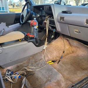
Have you checked the wiring from the inertia switch back into the dash? I’ve had issues with it melting at various spots.
I’m assuming you are grounding out the fuel pump wire on the ECM test connector when you are checking for voltage at the pump? Grounding that powers the relay constantly when the ignition is on, not just for a few seconds when the pumps prime.
Another common failure is the ground wire coming off the negative battery terminal, from the factory it would be one or two small wires that run off towards the firewall. Those provide ground for the fuel pump and computer.
")