• Welcome Visitor! Please take a few seconds and Register for our forum. Even if you don't want to post, you can still 'Like' and react to posts.

TDI Ranger Build


greengeeker

Member
Firefighter
Joined
Jul 12, 2012
Messages
227
Reaction score
9
Points
18
Location
Cambridge, MN
Engine Size
1.9L
Transmission
Manual
be controls has the auto trans covered.
Thanks for the lead bobby! Very reasonable prices.
what kind of coin to get to that?? anybody know for sure.??
Yes, I'll give a run down later of the mods needed to get to this point. As I pointed out earlier (in a couple spots): 1) this equates to a 800hp duramax so think of that in terms of what needs to be modified to make this amount of power reliably 2) He has crossed the magic 200hp threshold (for a tdi) which means he had to go into the lower end to beef things up as well as improve the breathing of the head.

Run down of mod list to get to this power level (hold onto your shorts :thefinger:):

from tdiclub build thread said:
AHH with 11mm IP $750
PD Lift pump free
Rosten H-beam rods $600
ASZ 18.5:1 PD pistons $750
R520 nozzles set to 230/340 bar $500
Stage 2 Colt cam $400
Ported head $800
GTB2056VL on a ported 1.6 TD manifold with adapter plate $1300
2.5" exhaust, 2 resonators
SBC Stage 2 endurance clutch
Upgraded head bolts and main bolts $150
EVOMS FMIC
Custom boost piping
Custom intake.
4bar map $100
Yeah, that's over $5k in performance parts. Keep in mind that you can get there cheaper (buying used parts, looking for deals, etc). I'll be posting my details later on the prices for the injection pump, exhaust manifold, turbo, injector nozzles, etc when I get there. It is NOT going to be anywhere near that expensive....closer to $1500 and I'll be nearing 200whp.
 
Last edited:

bobbywalter

TRS Technical Staff
TRS Event Staff
V8 Engine Swap
TRS Technical Advisor
TRS Banner 2012-2015
TRS 20th Anniversary
Ugly Truck of Month
TRS Event Participant
Joined
Aug 9, 2007
Messages
23,470
Reaction score
4,668
Points
113
Location
woodhaven mi
Vehicle Year
1988
Make / Model
FORD mostly
Engine Type
V8
Engine Size
BIGGER
Transmission
Automatic
2WD / 4WD
4WD
Total Lift
sawzall?
Tire Size
33-44
My credo
it is easier to fix and understand than "her"
for a 2wd commuter thats 5 k well spent imo. huge fun little hotrod diesel.


but not for me, i lean towards the less costly fuel end.
i have not had time to see about making one black fuel friendly but hope to by the end of summer.

the b2 sits more then it moves because its a little piglet on gas, so a tdi on regular fuel would be ok i think...once i get back to working that will change, i feel bad for the kids as thats their favorite car to drive.

thanks again for doing this and keeping so many details lined out:icon_thumby:
 

bobbywalter

TRS Technical Staff
TRS Event Staff
V8 Engine Swap
TRS Technical Advisor
TRS Banner 2012-2015
TRS 20th Anniversary
Ugly Truck of Month
TRS Event Participant
Joined
Aug 9, 2007
Messages
23,470
Reaction score
4,668
Points
113
Location
woodhaven mi
Vehicle Year
1988
Make / Model
FORD mostly
Engine Type
V8
Engine Size
BIGGER
Transmission
Automatic
2WD / 4WD
4WD
Total Lift
sawzall?
Tire Size
33-44
My credo
it is easier to fix and understand than "her"
hell jhon, i would have considered it but i am mobilizing to go start a job tomorrow.


on edit. i am back....and look here


http://www.cotybuilt.com/


this makes dropping a tdi in anything a cake walk.....so i am now seriously considering this.

1300 to get to a 1350 trans is a kick in the balls though. i think green can eliminate that threat.
 
Last edited:
greengeeker

Member
Firefighter
Joined
Jul 12, 2012
Messages
227
Reaction score
9
Points
18
Location
Cambridge, MN
Engine Size
1.9L
Transmission
Manual
Alternator wiring, continued


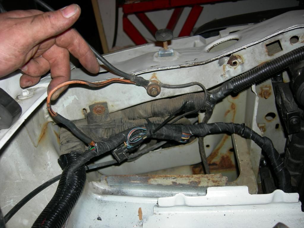
I'll tap into the harness upstream of this main connector. You can see the 'alt bulb' wire label which will end up at the ecu....I'll splice into this with my brown/red going downstream to the ecu and the blue one going upstream to the cluster. Will post more on this.

I added a few feet onto these two wires to reach the Ford harness near the firewall:


I found the same green/red alternator wire (the one labelled in the picture) in this bundle and spliced in my two wires. Pretty simple: cut the green/red wire and connect the brown/red wire to the half that goes to the ecu and the blue wire to the half that goes to the cluster. The following picture might be a little confusing...the large plug is the one that previously was attached to the firewall.


And with that we're done with the alternator wiring.
 

greengeeker

Member
Firefighter
Joined
Jul 12, 2012
Messages
227
Reaction score
9
Points
18
Location
Cambridge, MN
Engine Size
1.9L
Transmission
Manual
Glow Plug Relay

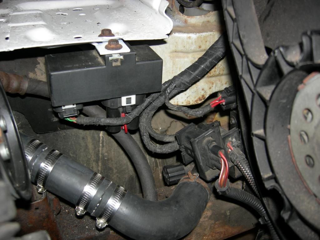
I really had trouble figuring out a good spot for my glow plug relay. I had considered installing the engine glow plug relay into the coolant glow plug relay housing but I really couldn't find a good spot for that large housing. I decided to mount it right near the battery junction box...where I'll be adding a 50A circuit to run the relay.

Here is the relay itself removed from the interior portion of the harness:


Wiring for this little guy:
BIG red wire > constant 12V 50A circuit
2 red/white > glow plugs
blue/yellow > switched 12V circuit
violet/white > ECU
green/white > ECU
Brown/red? > ground

All of these circuits are available in this trunk of the Ranger harness (just about every circuit runs through this part of the harness ) OR they need to be added...mainly the first one. More on this one.

Because my Ranger doesn't have ABS (and some other circuit) I have a few empty fuse slots:


First I had to run to the bone yard to pick myself up a battery junction box so I can steal the wires/connectors and install them into my junction box:

Here is the back of the junction box after some disassembly:


And here are the two empty slots:


More disassembly:


And here are the two added circuits:


Back to the glow plug relay. Now that I have the 50A power circuit I can connect it to the relay paying attention to length of wires and where I want my relay to end up. I stole 2 circuits from the EVAP purge valve in the engine bay to provide the switched power as well as one of the ECU circuits. The 2nd ECU circuit I simply tapped into in the harness, same story for the ground.


I'll probably shorten the red/white wires but will wait until I have everything in place.
 

greengeeker

Member
Firefighter
Joined
Jul 12, 2012
Messages
227
Reaction score
9
Points
18
Location
Cambridge, MN
Engine Size
1.9L
Transmission
Manual
Wiring Supplies

Before I go much further I'd like to give a quick run down of my wiring supplies:


I'm inclined to use adhesive-lined products to keep any moisture out of the joint. Both the heat-shrink tubing as well as my heat-shrink butt connectors have this feature. 3M makes both of them. I bought the heat shrink (EPS-300) and 3M friction tape (fabric covered electrical tape) from Grainger. For solder supplies I picked these up at Radio Shack: flux and 96/4 lead free, silver-bearing solder. I'm not a soldering expert so I'd recommend you consult one before using these specific supplies. :icon_thumby:
 

chucky2

Member
Joined
Sep 9, 2009
Messages
83
Reaction score
1
Points
8
Location
Chicagoland, IL USA
Vehicle Year
2003
Make / Model
Ford
Engine Size
4.0L SOHC V-6
Transmission
Automatic
Just curious, how long do you think until you've got this buttoned up and on the road?
 

greengeeker

Member
Firefighter
Joined
Jul 12, 2012
Messages
227
Reaction score
9
Points
18
Location
Cambridge, MN
Engine Size
1.9L
Transmission
Manual
I'm hoping for a maiden voyage in the next week or so. I've got lots of stuff going on with the fire dept right now.
 

greengeeker

Member
Firefighter
Joined
Jul 12, 2012
Messages
227
Reaction score
9
Points
18
Location
Cambridge, MN
Engine Size
1.9L
Transmission
Manual
Well I found out that it is really hard to top off your coolant when it comes pouring out of the heater box.:sad:
 

alwaysFlOoReD

Forum Staff Member
TRS Forum Moderator
TRS Banner 2012-2015
TRS 20th Anniversary
Joined
Apr 13, 2009
Messages
13,981
Reaction score
5,135
Points
113
Location
Calgary, Canada
Vehicle Year
'91, '80, '06
Make / Model
Ford, GMC,Dodge
Engine Size
4.0,4.0,5.7
Transmission
Manual
2WD / 4WD
4WD
OOPS is a four letter word.
 

greengeeker

Member
Firefighter
Joined
Jul 12, 2012
Messages
227
Reaction score
9
Points
18
Location
Cambridge, MN
Engine Size
1.9L
Transmission
Manual
Haha. Yes not that big of a deal. I'm just never crazy about replacing any heater core.
 

greengeeker

Member
Firefighter
Joined
Jul 12, 2012
Messages
227
Reaction score
9
Points
18
Location
Cambridge, MN
Engine Size
1.9L
Transmission
Manual
Fan control module wiring

Unfortunately I don't have too many pictures of my wiring process for the fan control module. Its wiring is fairly independant from the ecu and main engine harness save one wire. It relies on a few temp and pressure sensors to determine when to run the cooling fans (low or high speed) as well as the a/c compressor.

Here is what I started with:


Here is the pinout for the fan control module:

T4a/1.....ro/ws...cooling fan power (low speed)
T4a/2.....ro/sw...cooling fan power (high speed)
T4a/3.....ro........constant 12V 30A circuit
T4a/4.....ro/ws...constant 12V 40A circuit
T10b/1..............not used
T10b/2...ge/ro....a/c pressure switch
T10b/3...gn........ECU
T10b/4...ro/gr.....constant 12V 10A circuit
T10b/5...gn........a/c cutout thermal switch
T10b/6...br/sw....GROUND
T10b/7...ro/ge.....fan control thermal switch
T10b/8...gn.........a/c cutout thermal switch
T10b/9...sw/bl.....switched 12V 7.5A circuit
T10b/10..gn/sw...a/c clutch

I actually did not install a few of these components as I'm not setup for a/c just yet so I just zip tied those parts of the harness up and out of the way. I pre-wired everything in a similar fasion as I did with the main harness. The way I have it wired I should have the basic functionality of electric fans. All of my power circuits were ran back to the battery junction box and wired in as described in my glow plug relay post. For the switched power, I tapped into the same 12V power for my glow plug relay (before I wrapped everything of course). Ground as you can see in the following pictures is achieved via the main grounding point behind the battery.


I did run two wires through the main Ranger engine connector: the ECU signal wire (T10b/3) as well as the compressor power wire (T10b/10). For compressor ground I tapped into the crank case vent ground. Anyway, lots going with this one so study those wiring diagrams. :icon_thumby:
 

Sponsored Ad


Sponsored Ad

Staff online

Today's birthdays

Member & Vendor Upgrades

For a small yearly donation, you can support this forum and receive a 'Supporting Member' banner, or become a 'Supporting Vendor' and promote your products here. Click the banner to find out how.

Truck of The Month


Mudtruggy
May Truck of The Month

Recently Featured

Want to see your truck here? Share your photos and details in the forum.

Follow TRS On Instagram

TRS Events

25th Anniversary Sponsors

Check Out The TRS Store


Sponsored Ad


Sponsored Ad

Sponsored Ad


Amazon Deals

Top