• Welcome Visitor! Please take a few seconds and Register for our forum. Even if you don't want to post, you can still 'Like' and react to posts.

V8 swap, tcases.


Craig0320

Well-Known Member
Supporting Member
Article Contributor
V8 Engine Swap
TRS 20th Anniversary
Joined
Sep 21, 2017
Messages
1,209
Reaction score
225
Points
63
Location
Mississppi
Vehicle Year
1998
Make / Model
Ford
Engine Type
V8
Engine Size
5.0
Transmission
Automatic
2WD / 4WD
4WD
My credo
Break it right the first time. Fix it better the next time.
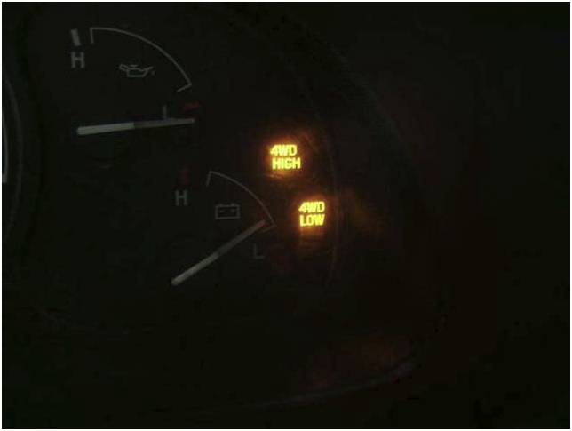
I didn't use the relay and just hooked the wires up direct. Both the 4hi and 4low lights came on when in 4lo. didn't bother me and I liked it that way.

Transfer Case Indicator Lights Hookup

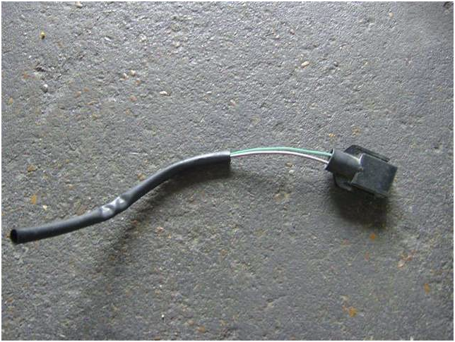
Using the Ford CD and a pigtail, I wired up the dash lights for my transfer case. It was easy.

Besides the case, obviously, you need:
• approx 10 feet of small gauge wire
• wire connectors

• relay (optional)

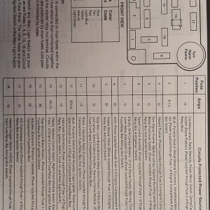
• wiring diagram of your vehicle

This is an easy job to do and in my opinion worth the effort.

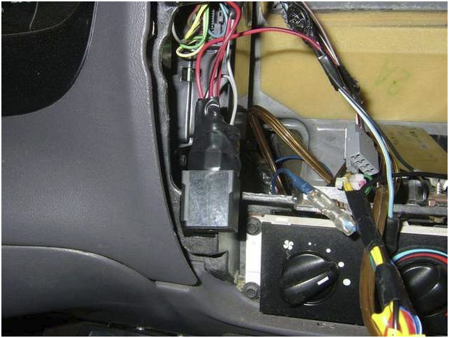
1. Remove the radio bezel, there are two screws under the radio to remove it, they are 7mm. Unhook all of the connectors that are hooked to the bezel.

2. Remove the radio if necessary. I have an aftermarket radio and it came out with the bezel.

3. On the left side of the hole in the dash, the GEM is mounted vertically.


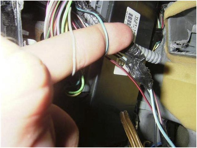
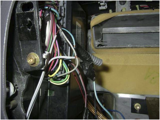
4. Using your wiring diagram, locate the two wires that go to the dash indicators. I would think many years would be similar, but Ford likes to change things up, so do your research. My wires were grey and light blue w/ black stripe.
1679445076101.png


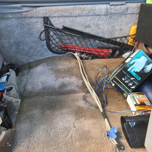
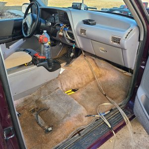
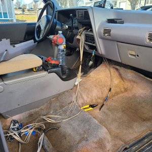
5. Now that you have the wires located run the wires from the dash to the bottom side of the body. I ran my wires under the carpet to a plug in the body about the size of a quarter that came out just on the outside of the frame on the drivers side.

6. Wire the wires to the two coming from the pigtail. It doesn't matter at this point which wire is which, so just hook them up.

1679445104592.png
1679445239133.png

1679445130770.png


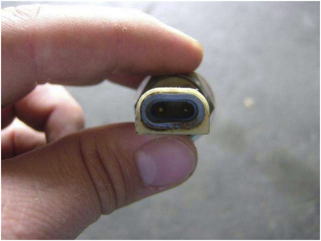
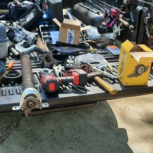
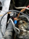
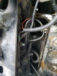
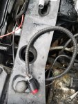
7. Find your shift indicator switch on the transfer case. It is near the shift fork and takes a 22mm hand wrench to remove.


8. Route the wire away from the driveshaft and plug it into the switch. I ran mine from the plug over the frame, over the shift linkage bar, behind the vent hose to ensure id doesn't get near the driveshaft.

9. Go back to the cab. The two wires that you found earlier you need to strip some insulation away from. I just took a wire stripper and cut and pushed the insulation.


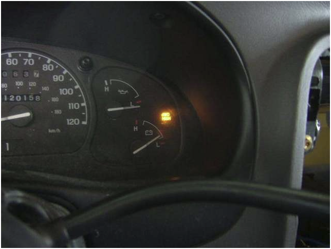
10. At this point, don't connect the wires permanantly. Pull your case into 4 hi. Taking one wire from the case at a time touch it to the wire that runs to the dash. Find the wire that lights up the 4 high light.

1679445260843.png
1679445301639.png


At this point, you need to decide if it will bother you to have both the high and low light on when the case in in low. The switch works by putting a ground signal when the case is in 4 high, when you pull it into 4 low, the 4 high light and the 4 low light will illuminate if you just hook up the wires. It works well enough I guess, but I wanted it to be correct. Using a standard relay, you can do some simple wiring to correct this.

If It doesn't bother you, hook the wires up and you are done.


1679445177001.png

EDIT: This sounds confusing, but I don't really know how to make it clearer. (I'm open to suggestions) Once you get in there, it should make more sense.

11. To wire the relay, find a 12v positive source. The wire for the cigar lighter comes from the GEM and will work for this. Wire the relay as follows-

12v + to the 85 post

Connect the wire from the transfer case that comes on when in 4 low to the 86 post

Connect the wire from the transfer case that comes on when in 4 high to the 30 post

Connect a wire from the 87a post to the wire that goes to the 4 high light

12. Connect the wire from the case that comes on when in 4 low to the wire that goes to the 4 low dash light.

The way this works is, the ground from the 4 low signal trips the relay, cutting the signal to the 4 high light. The 4 high light now only works when in 4 high.


Thats it, put the radio and bezel back and your done!


85_Ranger4x4

Forum Staff Member
TRS Event Staff
TRS Forum Moderator
Article Contributor
V8 Engine Swap
OTOTM Winner
TRS Banner 2010-2011
TRS 20th Anniversary
VAGABOND
TRS Event Participant
Joined
Aug 7, 2007
Messages
32,376
Reaction score
17,939
Points
113
Location
SW Iowa
Vehicle Year
1985
Make / Model
Ford
Engine Type
V8
Engine Size
5.0
Transmission
Manual

Craig0320

Well-Known Member
Supporting Member
Article Contributor
V8 Engine Swap
TRS 20th Anniversary
Joined
Sep 21, 2017
Messages
1,209
Reaction score
225
Points
63
Location
Mississppi
Vehicle Year
1998
Make / Model
Ford
Engine Type
V8
Engine Size
5.0
Transmission
Automatic
2WD / 4WD
4WD
My credo
Break it right the first time. Fix it better the next time.

Tomm1468

Active Member
V8 Engine Swap
Joined
Apr 22, 2021
Messages
105
Reaction score
45
Points
28
Location
Spokane, WA
Vehicle Year
2000
Make / Model
Ranger XLT
Engine Type
V8
Engine Size
5.0
Transmission
Automatic
2WD / 4WD
4WD
Total Lift
3"
Tire Size
245/75R16
Alrighty, so I have my V8 installed into my 2000 Ranger. everything is wired up and ready. Unfortunately, i cant get it to start. I have a good power supply, i got the PATS deleted off my new 5.0 computer so I dont think that is the problem. It does crank, just wont go. I can hear the fuel pump coming on, and I have double checked all the wiring for everything. Not sure if maybe the PATS is still acting up, or what it actually controls, My next thought is to check my injectors for pulse, and my spark wires for pulse too. does anyone have any other suggestions?

also, something I thought was weird, my check engine light is on from the second I turn the key, is that normal? It just seemed weird to me since I have had my battery disconnected up until this second, it shouldn't be on ?
 

RonD

Official TRS AI
TRS Technical Advisor
Joined
Jun 2, 2012
Messages
25,363
Reaction score
8,372
Points
113
Location
canada
Vehicle Year
1994
Make / Model
Ford
Transmission
Manual
Do 50/50 test
Spray fuel into the intake
Try to start
If it starts, runs and dies then you have fuel delivery issue
If it doesn't fire then its a spark issue
50/50 instant results


CEL should come on with key on, that means computer has booted up
CEL should go OFF when cranking engine over, this mean computer is getting a good Timing Signal from Crank Sensor, so will start spark and then fuel injectors
If CEL is not going off while cranking check to make sure crank sensor got plugged in
 

Tomm1468

Active Member
V8 Engine Swap
Joined
Apr 22, 2021
Messages
105
Reaction score
45
Points
28
Location
Spokane, WA
Vehicle Year
2000
Make / Model
Ranger XLT
Engine Type
V8
Engine Size
5.0
Transmission
Automatic
2WD / 4WD
4WD
Total Lift
3"
Tire Size
245/75R16
thanks for the advice, i tried it out, and still no signs of life, so i decided to switch out my battery just for the heck of it, and (KABLAMMMO!!) i got the first start on my engine after having to completely rebuild, sounds great too! I guess my "SOLID POWER SUPPLY" wasn't so solid after all.
 

Tomm1468

Active Member
V8 Engine Swap
Joined
Apr 22, 2021
Messages
105
Reaction score
45
Points
28
Location
Spokane, WA
Vehicle Year
2000
Make / Model
Ranger XLT
Engine Type
V8
Engine Size
5.0
Transmission
Automatic
2WD / 4WD
4WD
Total Lift
3"
Tire Size
245/75R16
Craig,

sorry for all the questions, it's just that your article is almost step by step everything i am doing, with a few small differences.
what did you do with the a/c wire? i have the wire cut right as its coming out past the radiator, do i take that half and combine it with the other a/c wire that's just right there plugged in?
I'm on the last few steps of setting things up, one of them being cutting a hole for the manual shifter of the new 4406. do you have anything you wish you did or did not do with the cuts/ install on that.
also, i seem to have misplaced the two bolts that screw the transfer case shifter to the transmission, to hold it in place, do you know what size those bolts are?
thanks again for all your help, you've been extremely helpful.
 

Craig0320

Well-Known Member
Supporting Member
Article Contributor
V8 Engine Swap
TRS 20th Anniversary
Joined
Sep 21, 2017
Messages
1,209
Reaction score
225
Points
63
Location
Mississppi
Vehicle Year
1998
Make / Model
Ford
Engine Type
V8
Engine Size
5.0
Transmission
Automatic
2WD / 4WD
4WD
My credo
Break it right the first time. Fix it better the next time.
Ask as many questions as you like. That's how I built mine. These quotes are straight out of the article because everything is explained the best I feel. Pay attention to italics and bold closely they are the important information. The high pressure a/c switch is on the back of the ranger compressor. It comes out of the main harness on the driver's side of the radiator on the Explorer and the black wire/white stripe grounds to a stud next to it with the ground from the negative battery terminal.


So I found the red wire/ yellow stripe(a/c signal wire for high pressure switch) in the ranger harness to the right of the radiator. I spliced into it and wired the explore high pressure switch plug to it. The black wire/white stripe goes to ground. I grounded it right back to the lug with the negative battery terminal wire.


Solenoid wire plug
This plug is right underneath the lines that come off the abs.

The explorer and the ranger plug do not match up. (I think they were both male)
The Ranger plug has 5 wires
Yellow/white strip (Starter solenoid wire)
Red/yellow strip (signal wire high/low pressure a/c switch)
Black-white strip (ground for high/low pressure a/c switch)
Gray/white stripe(a/c clutch relay signal wire)
Black wire(a/c clutch relay ground wire)
Explorer plug has 3 wires
Yellow/white strip (Starter solenoid wire)
Gray/white stripe(a/c clutch relay signal wire)
Black wire(a/c clutch relay ground wire)

The reason the other two are not in there is because they come out by the radiator. So just wire up the 3 wire plug from the explorer and your good to go


As stated above this information is the best I can explain it. I know reading all the information at once sometimes it all blends together. Plus I built it in 2017 lol. Memory isn't the best any more. I'm working on getting some pictures attached that I found of the ac plug.
I don't know the bolt sizes for you are looking for. I have a bucket of bolts and usually find what I need in there lol.
 

Craig0320

Well-Known Member
Supporting Member
Article Contributor
V8 Engine Swap
TRS 20th Anniversary
Joined
Sep 21, 2017
Messages
1,209
Reaction score
225
Points
63
Location
Mississppi
Vehicle Year
1998
Make / Model
Ford
Engine Type
V8
Engine Size
5.0
Transmission
Automatic
2WD / 4WD
4WD
My credo
Break it right the first time. Fix it better the next time.
Here are some pics of the ac plug. It shows where I wired it up at.
 

Attachments

Tomm1468

Active Member
V8 Engine Swap
Joined
Apr 22, 2021
Messages
105
Reaction score
45
Points
28
Location
Spokane, WA
Vehicle Year
2000
Make / Model
Ranger XLT
Engine Type
V8
Engine Size
5.0
Transmission
Automatic
2WD / 4WD
4WD
Total Lift
3"
Tire Size
245/75R16
Alrighty, So i have everything installed, minus exhaust pipes, 02 sensors, and a drive shaft. My engine, however seems to be running super weird, super weird that I have no experience in. it starts up slow cranking a little at first. then starts up. my tachometer reads it idling at about 2000 rpms then moving to about 1500 when warm, but my computer live data shows it starting at about 1000 and moving down to the high 700's. from the sound of it, it sounds like the tachometer is right.
Furthermore, when I rev it up it will do one of two things, once I get it up to around 3000 rpms on the tachometer, it will stall out, and die. Or it will go up, but my live data shows only around 1500 rpms, which I have not been able to move past no matter how high I rev. I'm not actually sure where the computer gets its data, but I guessed the crank position sensor. I got a new one when i rebuilt the engine, so I ordered another one, this time a Motorcraft piece. hoping that will solve things.

I also noticed it shakes a little when getting up in the Rpms, so I tested all the fuel injectors, all are working and strong, I got new coil packs and spark wires, and I already had new bosch spark plugs, but its still shaking a little. I read online that failing crank sensor could cause this.

last ( i know this is a lot all at once) when I have my MAF plugged in it tends to bob for a minute, then die once warmed up. I am assuming the MAF is just dirty and will be trying to clean it, because it idles smooth again once its unplugged, but I also cant help but think its my lack of 02 sensors, and the fact that my EGR is probably pulling in outside air, since nothing is connected to the exhaust manifold, but idk.

any ideas would be great, thanks.
 

RonD

Official TRS AI
TRS Technical Advisor
Joined
Jun 2, 2012
Messages
25,363
Reaction score
8,372
Points
113
Location
canada
Vehicle Year
1994
Make / Model
Ford
Transmission
Manual
Last first
Without O2 sensor feedback once engine warms up computer is lost, unplugging MAF sensor puts it back into OPEN Loop so it's not trying to adjust fuel trims on the fly it just uses pre-programmed air/fuel ratios like it does when engine is cold

Get the 2 Upstream O2 sensors working before trying to diagnose engine running issues
And replace them if they are older than 12 years, O2s are the only sensors that have a use/time limit, 12 years or 100k miles

Tachometer
You have to change the ground wires on the back of instrument cluster to V8 setting
Only Pin 16 of the 16-pin grounded ==> V8
Only Pin 8 of the 10-pin grounded ==> V6
Neither grounded ==> 4cyl

Applies to 1996-2003 clusters

So if it was/is a 3.0l/V6 cluster then unpin pin 8 on 10pin connector and move that ground wire to pin 16 on 16pin connector
Pins are easy to release and move
Google: repin Ford connectors

Most use a spring tab or tabs, from the plug side you slide in a paperclip or small screwdriver to push the tab back and wire with pin pulls out
You push it back in to the new slot and tab springs out holding it in place
 

Tomm1468

Active Member
V8 Engine Swap
Joined
Apr 22, 2021
Messages
105
Reaction score
45
Points
28
Location
Spokane, WA
Vehicle Year
2000
Make / Model
Ranger XLT
Engine Type
V8
Engine Size
5.0
Transmission
Automatic
2WD / 4WD
4WD
Total Lift
3"
Tire Size
245/75R16
Thanks Ron, I have actually already redone the wiring on the tach, though, I may have not done it right, Ill pull the cluster today and check it.
honestly based on sound, it sounded like the tach was right to me and computer reading was wrong, but that doesnt make much sense to me.
 
Last edited:

RonD

Official TRS AI
TRS Technical Advisor
Joined
Jun 2, 2012
Messages
25,363
Reaction score
8,372
Points
113
Location
canada
Vehicle Year
1994
Make / Model
Ford
Transmission
Manual
The computer uses Crank Sensor(pins21/22) for RPM and sends that out to Tach(pin48) tan/yellow wire to cluster, pin15 on 16pin connector, so the V8 tach ground should be right next to it on pin16

Computer RPM is more likely to be correct based on the pathway but.................you are there :)
 

Tomm1468

Active Member
V8 Engine Swap
Joined
Apr 22, 2021
Messages
105
Reaction score
45
Points
28
Location
Spokane, WA
Vehicle Year
2000
Make / Model
Ranger XLT
Engine Type
V8
Engine Size
5.0
Transmission
Automatic
2WD / 4WD
4WD
Total Lift
3"
Tire Size
245/75R16
I feel dumb, I pulled the cluster, and found my wire had come out, I stuck is back in and the tach lowered itself down to about 50 to 100 above what the computer was reading. You were right, glad I listened, even though I thought it was not quite right.
 

Tomm1468

Active Member
V8 Engine Swap
Joined
Apr 22, 2021
Messages
105
Reaction score
45
Points
28
Location
Spokane, WA
Vehicle Year
2000
Make / Model
Ranger XLT
Engine Type
V8
Engine Size
5.0
Transmission
Automatic
2WD / 4WD
4WD
Total Lift
3"
Tire Size
245/75R16
Ask as many questions as you like. That's how I built mine. These quotes are straight out of the article because everything is explained the best I feel. Pay attention to italics and bold closely they are the important information. The high pressure a/c switch is on the back of the ranger compressor. It comes out of the main harness on the driver's side of the radiator on the Explorer and the black wire/white stripe grounds to a stud next to it with the ground from the negative battery terminal.


So I found the red wire/ yellow stripe(a/c signal wire for high pressure switch) in the ranger harness to the right of the radiator. I spliced into it and wired the explore high pressure switch plug to it. The black wire/white stripe goes to ground. I grounded it right back to the lug with the negative battery terminal wire.


Solenoid wire plug
This plug is right underneath the lines that come off the abs.

The explorer and the ranger plug do not match up. (I think they were both male)
The Ranger plug has 5 wires
Yellow/white strip (Starter solenoid wire)
Red/yellow strip (signal wire high/low pressure a/c switch)
Black-white strip (ground for high/low pressure a/c switch)
Gray/white stripe(a/c clutch relay signal wire)
Black wire(a/c clutch relay ground wire)
Explorer plug has 3 wires
Yellow/white strip (Starter solenoid wire)
Gray/white stripe(a/c clutch relay signal wire)
Black wire(a/c clutch relay ground wire)

The reason the other two are not in there is because they come out by the radiator. So just wire up the 3 wire plug from the explorer and your good to go


As stated above this information is the best I can explain it. I know reading all the information at once sometimes it all blends together. Plus I built it in 2017 lol. Memory isn't the best any more. I'm working on getting some pictures attached that I found of the ac plug.
I don't know the bolt sizes for you are looking for. I have a bucket of bolts and usually find what I need in there lol.

what did you use for the rear drive shaft on this swap? i read through your article and didn't see too much mentioned on it. I measured and it looks like i'd need an overall drive shaft length of about 60" including the slip yoke. I searched through all the F150 drive shafts I could find in that 1997 -2003 range and there doesnt seem to be any that are really even close to that length. I'm thinking ill just get the 69 incher and slice off what I don't need then have it welded. thoughts??
 

Sponsored Ad


Sponsored Ad

Staff online

Today's birthdays

Member & Vendor Upgrades

For a small yearly donation, you can support this forum and receive a 'Supporting Member' banner, or become a 'Supporting Vendor' and promote your products here. Click the banner to find out how.

Truck of The Month


Mudtruggy
May Truck of The Month

Recently Featured

Want to see your truck here? Share your photos and details in the forum.

Follow TRS On Instagram

TRS Events

25th Anniversary Sponsors

Check Out The TRS Store


Sponsored Ad


Sponsored Ad

Sponsored Ad


Amazon Deals

Top