• Welcome Visitor! Please take a few seconds and Register for our forum. Even if you don't want to post, you can still 'Like' and react to posts.

Need guidance on removing wires, etc. for duraspark convert? Pictures.


franklin2

Well-Known Member
Joined
Dec 24, 2019
Messages
3,428
Reaction score
1,758
Points
113
Location
Virginia
Vehicle Year
1984
Make / Model
Bronco II
Transmission
Manual
He shouldn't need to buy a resistor. You can see in the diagram you posted there is already a ignition resistor built into the harness. You are correct, find the correct connector, and you should be good to go. Do not mess this connector up. If you are going to use a Druaspark box later on, it will plug right into this connector you are going to temp use. The duraspark needs the resistor as well as your points system, thus why Ford already put it in the harness


franklin2

Well-Known Member
Joined
Dec 24, 2019
Messages
3,428
Reaction score
1,758
Points
113
Location
Virginia
Vehicle Year
1984
Make / Model
Bronco II
Transmission
Manual
EVAP solenoid power wire is the one I use for 12v to electric choke. 👍
That will work fine except there will be the rare occasion when the engine possibly is hard to start. As you are messing around with a stubborn engine, the key tends to get left on. So as you are cranking and it's not starting, the choke is heating up and pulling off, making a stubborn starting engine even more stubborn to start. It rarely happens, but the factory accounted for it. If someone turned the key on to listen to the radio, that would be another situation where it would be hard to start becuase the choke has already pulled off.

Ford used the alternator stator output on most of their vehicles. GM used a oil pressure switch on some of their vehicles.
 

tw205

Bronco II Rancher.
U.S. Military - Veteran
Joined
Jan 23, 2011
Messages
730
Reaction score
976
Points
93
Location
Bronson Michigan
Vehicle Year
1985
Make / Model
Ford Bronco II
Engine Type
2.8 V6
Engine Size
2.8
Transmission
Manual
2WD / 4WD
4WD
Total Lift
6” skyjacker 2” body
Tire Size
33x12.5
That will work fine except there will be the rare occasion when the engine possibly is hard to start. As you are messing around with a stubborn engine, the key tends to get left on. So as you are cranking and it's not starting, the choke is heating up and pulling off, making a stubborn starting engine even more stubborn to start. It rarely happens, but the factory accounted for it. If someone turned the key on to listen to the radio, that would be another situation where it would be hard to start becuase the choke has already pulled off.

Ford used the alternator stator output on most of their vehicles. GM used a oil pressure switch on some of their vehicles.
True if you left the key on in run while working on said stubborn engine but, with the key in the acc position listening to the radio there is no power applied to the old EVAP circuit.
 

RobbieD

2.9l Mafia
Joined
Aug 6, 2007
Messages
3,887
Reaction score
3,465
Points
113
Location
Georgia
Vehicle Year
1984,1990,1994
Make / Model
Ford
Transmission
Manual
2WD / 4WD
2WD
My credo
Toonces drives a Ranger . . . . just not very well.
He shouldn't need to buy a resistor. You can see in the diagram you posted there is already a ignition resistor built into the harness.
The 4-cylinders' MCU wiring harness uses a resistor wire on the "run" leg, but the EEC wiring harness for the 2.8 didn't. I remember getting a full +12 volts on both "start" and "run" legs when I did mine, and being confused about that until I noticed the difference in the wiring harnesses in the schematics.

So, I posted both diagrams, to show how Ford did it originally- full power for TFI distributors, lower power in "run" for non-TFI distributors.

I've run a ballast resistor on mine without any issues (converted in 2009), and the coil gets around +9v in "run". I've run both a stock coil and a can coil in this truck.
 

franklin2

Well-Known Member
Joined
Dec 24, 2019
Messages
3,428
Reaction score
1,758
Points
113
Location
Virginia
Vehicle Year
1984
Make / Model
Bronco II
Transmission
Manual
Sorry I goofed. I have the larger f150 trucks down in my memory banks, but looked at little closer at your TFI diagram which I assume is for the smaller trucks, and the resistor is not present in the TFI diagram.

P.S. What year TFI diagram is that above? I just looked at my 1984 Bronco II EVTM and it had TFI and DOES have the resistor. They just have a wire around it to bypass it depending on what ignition you use. But of course they never had a 4 cyl BII, so my diagrams do not show a DSII version.
 
Last edited:

RobbieD

2.9l Mafia
Joined
Aug 6, 2007
Messages
3,887
Reaction score
3,465
Points
113
Location
Georgia
Vehicle Year
1984,1990,1994
Make / Model
Ford
Transmission
Manual
2WD / 4WD
2WD
My credo
Toonces drives a Ranger . . . . just not very well.
Sorry I goofed. I have the larger f150 trucks down in my memory banks, but looked at little closer at your TFI diagram which I assume is for the smaller trucks, and the resistor is not present in the TFI diagram.

P.S. What year TFI diagram is that above? I just looked at my 1984 Bronco II EVTM and it had TFI and DOES have the resistor. They just have a wire around it to bypass it depending on what ignition you use. But of course they never had a 4 cyl BII, so my diagrams do not show a DSII version.
Don't sweat it, man. I was confused and missed it at first too.

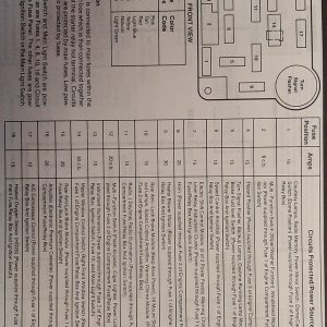
The schematics that I posted above come from the 1984 Ranger / Bronco II EVTM. This is the blue cover EVTM, publication number 0334-524-84.

The 1984 Bronco II EVTM that you're looking at; it has a green cover and pub no 0334-528-84, right? I have both, and the ignition diagram in the green B2 EVTM DOES show a resistor wire on the Red/L Grn "run" wire, AND it also shows a TFI distributor. This contradicts the blue cover manual.

So there is a definite discrepancy between these two manuals, and it very much looks like it's a factory typo. In my case, when Durasparking my '84 Ranger I was puzzled by the full +12 volts in both key position ("run" and "start") when I was verifying the wiring. That's when I found resistor wire difference in the EEC and MCU systems in the blue EVTM. That's why I added the ballast resistor, and it worked out fine.

Unlike most Ford manuals, neither of these 1984 EVTMs are dated on the back cover, though the green B2 book does state on the very first page the manual covers features introduced in January 1983. I'd have to go through my files for accurate dates, but I know that the 2.8 V6 came out sometime after the 1983 Ranger's release, and of course the B2 didn't appear until the 1984 models.

I love using the Ford factory manuals, but even they do have the occasional typo. In '82 though '84 the Ranger was selling like hotcakes, and there was a lot of pressure to get the B2 to market, so I can understand some typos slipping through.
 

franklin2

Well-Known Member
Joined
Dec 24, 2019
Messages
3,428
Reaction score
1,758
Points
113
Location
Virginia
Vehicle Year
1984
Make / Model
Bronco II
Transmission
Manual
Yes, I have the green manual.
 

Doug Burgoyne

Member
Joined
Oct 3, 2023
Messages
60
Reaction score
23
Points
8
Location
Oregon
Vehicle Year
1984
Make / Model
Ford Ranger
Transmission
Automatic
UPDATED...again! Sorry folks
Still lost here on coil wire issue.
..............................................................
Seems to be some serious previous owner hackery going on or something. The c102 plug is were my oil sender, temp sensor, and 2 alternator wires terminate, correct? The two end slots there are no wires as mentioned such as red/L grn and brn/pink. Just empty holes with spider nests! If I probe with my meter, the bottom one in picture has 12 volts with key on. The top one nothing with key on, but around 9.5 volts when cranking. Would make more sense the other way around, run at 9.5 if resistor in harness, and full 12 v when cranking. I noticed the two wires on this plug (other than the 4 noted above) that were quite dirty. Cleaned them up and one appears to be brown with pink stripe. The other red with yellow markings that I suppose could have been light green back in the day. See picture. The 2 wires I'm holding in fingers. The brown/pink has 9.8v when engine cranking but nothing with key on position. The red/yellow wire has nothing on either crank nor on positions. Still need to come up with strategy to get power to coil...no prob adding resistor wire as previously suggested. Ideas gentleman? Thanks to you all!
 

Attachments

Last edited:

RobbieD

2.9l Mafia
Joined
Aug 6, 2007
Messages
3,887
Reaction score
3,465
Points
113
Location
Georgia
Vehicle Year
1984,1990,1994
Make / Model
Ford
Transmission
Manual
2WD / 4WD
2WD
My credo
Toonces drives a Ranger . . . . just not very well.
HOLD ON THIS. May have figured out.
You're making good progress.

In case it helps, here's a "cheat sheet" I made on C102:

C102 notes image.JPG


Brn/Pnk should actually say "+12v in START and RUN".

When you meter the wire again, try pulling the small wire off the starter relay (AKA "solenoid") so that the starter doesn't engage with the switch in "start". Your battery may be tired, and the load from the starter engaging could cause a misleading voltage drop on the ignition wire that you're trying to measure.
 

franklin2

Well-Known Member
Joined
Dec 24, 2019
Messages
3,428
Reaction score
1,758
Points
113
Location
Virginia
Vehicle Year
1984
Make / Model
Bronco II
Transmission
Manual
If you want to buy a resistor, just use the original coil + wire that the engine was using. I think it's white/blue stripe.
 

Doug Burgoyne

Member
Joined
Oct 3, 2023
Messages
60
Reaction score
23
Points
8
Location
Oregon
Vehicle Year
1984
Make / Model
Ford Ranger
Transmission
Automatic
As always, I appreciate every second you spend typing to assist on this project! RobbieD, your cheat sheet is super helpful, but I'm not seeing the red/L grn wire on the sheet. Is that somewhere else? I will put battery on charger to top it off, and disconnect wire from relay as suggested. Is it the one on bottom in this pic, that goes down to starter? But I'm sure my brown/pink is only powered in crank position at ignition switch. Odd?
 

Attachments

Doug Burgoyne

Member
Joined
Oct 3, 2023
Messages
60
Reaction score
23
Points
8
Location
Oregon
Vehicle Year
1984
Make / Model
Ford Ranger
Transmission
Automatic
Franklin2,
Are you refering to the wire going to original 2 prong coil plug? I still have plug and stub by coil, but that wire went into the large bundle that goes through firewall to ecm...so it's gone now. I'll be glad to have a plan figured out for coil power. Still a mystery....and who knows what was done by PO...I saw some dubious splicing here and there in the conduits.
 

RobbieD

2.9l Mafia
Joined
Aug 6, 2007
Messages
3,887
Reaction score
3,465
Points
113
Location
Georgia
Vehicle Year
1984,1990,1994
Make / Model
Ford
Transmission
Manual
2WD / 4WD
2WD
My credo
Toonces drives a Ranger . . . . just not very well.
Franklin2,
Are you refering to the wire going to original 2 prong coil plug? I still have plug and stub by coil, but that wire went into the large bundle that goes through firewall to ecm...so it's gone now. I'll be glad to have a plan figured out for coil power. Still a mystery....and who knows what was done by PO...I saw some dubious splicing here and there in the conduits.
Brn/Pnk and Red/L Grn should be crimped together in the terminal of C102 on the cab side. That ties the two circuits together (one hot in "run", the other hot in "start"). On the other mated connector of C102, on the engine side, the single wire carrying these combined circuits is supposed to Brn/Pnk, but it can also be Red/L Grn or Wht/Blu. This is the original coil power wire.

<edit> You can see this in the first wiring diagram that I put in post 15.

I found on mine, wire colors can look very different because of age and heat, but pulling fresher wire out of the loom or harness tape shows the true colors better.

On you starter relay, just pull straight out on the red rubber connector with the single small wire.
 

Doug Burgoyne

Member
Joined
Oct 3, 2023
Messages
60
Reaction score
23
Points
8
Location
Oregon
Vehicle Year
1984
Make / Model
Ford Ranger
Transmission
Automatic
Yes, wire colors can look very different and I've been doing same thing, tracing back further to get truer colors. I get what you're saying now on cab side and engine side of plug...was having brain fart there. Will see what I got, and will check voltages with topped off battery, and unplugged wire at starter relay. Thanks man!!
 

RobbieD

2.9l Mafia
Joined
Aug 6, 2007
Messages
3,887
Reaction score
3,465
Points
113
Location
Georgia
Vehicle Year
1984,1990,1994
Make / Model
Ford
Transmission
Manual
2WD / 4WD
2WD
My credo
Toonces drives a Ranger . . . . just not very well.
Take your time; it'll come together.

Good luck!
 

Sponsored Ad


Sponsored Ad

Staff online

Members online

Member & Vendor Upgrades

For a small yearly donation, you can support this forum and receive a 'Supporting Member' banner, or become a 'Supporting Vendor' and promote your products here. Click the banner to find out how.

Truck of The Month


Shran
April Truck of The Month

Recently Featured

Want to see your truck here? Share your photos and details in the forum.

Follow TRS On Instagram

TRS Events

25th Anniversary Sponsors

Check Out The TRS Store


Sponsored Ad


Sponsored Ad

Sponsored Ad


Amazon Deals

Top